
Blog
Caterpillar Liner Protrusion Measurement Steps
Precision cylinder block deck metrology guidelines for commercial diesel mechanics and fleet rebuilders.

Preparing a Caterpillar engine block deck for head installation during a major rebuild? Follow this step-by-step professional workshop procedure to clamp liners into place, zero the ATC 1P-2402 metric dial indicator on the deck surface, sweep four points per liner flange, calculate average protrusion, and select counterbore shims cleanly.
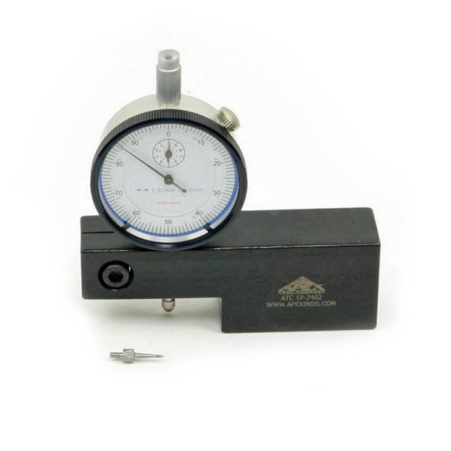
Why "Unclamped" Liner Measurements Cause Catastrophic Engine Failures
On Caterpillar heavy-duty diesel engines, cylinder liners sit inside precision counterbores machined into the block deck. Because rubber lower O-rings and liner seals exert upward pressure against the liner body, measuring liner height without hold-down bolts clamps yields completely false readings. Unclamped liners float upward by several thousandths of an inch, deceiving the technician into believing protrusion is correct when the liner is actually sitting too low in its counterbore seat. Once the cylinder head is torqued down, the liner compresses onto counterbore scale, dropping below factory spec and loosening head gasket fire ring crush. Furthermore, measuring at only one point on the liner flange hides counterbore seat tilt. If a counterbore seat is worn unevenly, the liner cocks sideways, causing localized liner flange bending and cracking under full cylinder head bolt torque. Utilizing the 2.00-pound ATC 1P-2402 Sled Gauge with Metric Dial Indicator eliminates these measurement mistakes entirely. By installing liner hold-down bolts and washers to full spec torque, cleaning the deck face, zeroing the sled on the block deck, and taking readings at 90-degree intervals around each liner flange, technicians obtain true, clamped protrusion data to ensure flawless head gasket sealing.
The 5-Step Caterpillar Liner Protrusion Measurement Protocol
- Install Liners & Apply Clamping Force: Clean counterbores thoroughly. Lower liners into block bores (without lower O-rings for dry test fitting). Install hold-down bolts and heavy washers across adjacent liner flanges and torque to OEM clamp specifications.
- Clean Block Deck & Zero ATC 1P-2402 Gauge: Wipe the engine deck face completely clean of oil, rust, and debris with a stone and solvent. Place the ATC 1P-2402 sled base flat on the deck surface and zero the metric dial indicator face.
- Slide Gauge Tip onto Liner Flange: Carefully slide the sled assembly so the metric dial indicator contact tip moves off the deck and onto the top surface of the cylinder liner flange. Read and record the protrusion value.
- Measure 4 Opposing Points Per Cylinder Liner: Rotate the ATC 1P-2402 gauge 90 degrees around the liner, taking protrusion measurements at four opposing quadrant points (Front, Back, Left, Right). *Verify that the variation between points on a single liner does not exceed CAT maximum tilt specifications.*
- Calculate Average Protrusion & Select Shims: Calculate the average protrusion value for each cylinder. If protrusion is below OEM spec or varies excessively across adjacent liners, cut the counterbore using a counterbore tool and install appropriate Caterpillar stainless steel shims to restore exact factory height.
- Final Verification: Remove hold-down bolts, install new lower seals and O-rings, re-clamp liners, and re-verify final protrusion with the ATC 1P-2402 gauge before installing the head gasket and cylinder head.
PRO-TECH LINER CLAMPING & DECK CLEANLINESS MANDATE:
ALWAYS TORQUE LINER HOLD-DOWN BOLTS TO SPEC before measuring protrusion! Measuring unclamped liners WILL result in incorrect shim selection and blown head gaskets! ALWAYS STONE BLOCK DECKS FLAT to ensure the ATC 1P-2402 sled base sits 100% flush without rocking on burrs or carbon!
2.00 lbs Precision Sled Base & Metric Dial Indicator. Protect Caterpillar Overhauls.
Get the ATC 1P-2402 Gauge Now
overall rating:
my rating:
log in to rate