Tech Guide: Synchronizing Mechanical John Deere Fuel Systems
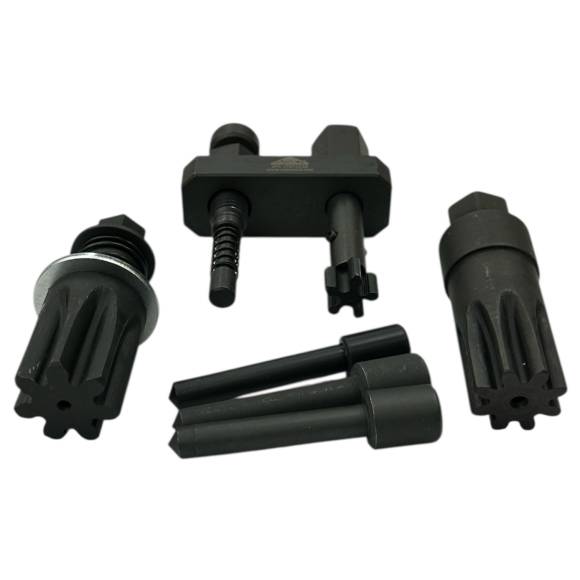
Prepping a mid-range John Deere agricultural block for a fresh injection pump? Master the strict mechanical sequence required to lock your timing train using the JT07223A pin assembly.
Why Gear Train Backlash Demands Absolute Component Pinning
The front timing gear train on a John Deere 4239 or 6359 diesel engine transfers rotational energy across multiple heavy meshes. Over time, normal gear backlash introduces subtle movement within the valvetrain assembly. When you loosen an injection pump drive gear or pull a camshaft without locking the system down, this built-in play can cause the gear positions to shift slightly. This shifts the fuel delivery injection window away from the optimal piston stroke position. Tapping loose bolts or generic screws into the timing holes is an absolute trap—these makeshift pins can bend or fit loosely, leading to alignment errors. Utilizing a precision-ground, hardened tool steel indexing set like the JT07223A physically centers the component hubs within the factory timing channels, keeping your engine exactly on specification throughout the overhaul.
The 5-Step Engine Synchronization Protocol
- Access Port Cleanout & Setup: Turn off all machine power and let the engine cool down completely. Remove the access caps on the engine flywheel housing and the front timing gear cover. Clean out these ports with solvent to clear away oil varnish and debris.
- Locate Top Dead Center (TDC): Rotate the engine crankshaft slowly by hand in the direction of normal operation until the primary cylinder piston hits Top Dead Center on its compression stroke. Watch for the internal timing marks to align inside the open housing port.
- Engage the Crankshaft Lock: Slide the precision-machined JT07223A flywheel alignment pin straight into the housing index bore. Turn the crank slightly until the pin drops into the flywheel timing notch, locking the crankshaft at TDC.
- Pin the Camshaft & Fuel Pump Hubs: Insert the designated JT07223A indexing components into the camshaft gear and injection pump hub ports. The pins should slide in smoothly without force. If you feel resistance, the components are out of alignment and require adjustment. Keep these pins in place while removing or installing parts.
- Final Gear Torquing & Verification: Bolt down your drive gears and injection pump mounts to factory torque specifications while the pins lock the train in place. Once torqued, pull all the JT07223A alignment tools from the block. Rotate the crankshaft two full manual turns by hand and verify that the pins still drop back into their indexing positions before starting the engine.
PRO-TECH MECHANICAL COMPLIANCE RULE:
Never use any force or starter motor engagement to turn the engine while an alignment pin from the JT07223A kit is installed in the flywheel or gear train holes. The structural steel pins are designed for static alignment control only. High rotational forces will bend the precision pins or crack the cast aluminum engine housing.