
Blog
Cummins NT & N14 Cylinder Liner Puller & Press Steps
Precision engine rebuilding guidelines for heavy diesel technicians and fleet overhaul mechanics.
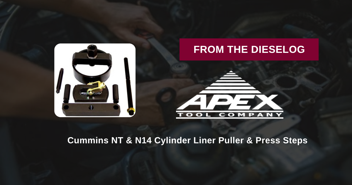
Overhauling a Cummins NT or N14 diesel engine in-frame or on a rebuild stand? Follow this step-by-step professional workshop procedure to extract stubborn 5.5" wet liners using the M20105 puller, clean block counterbores, lubricate fresh O-rings, and press new liners down to achieve precise protrusion heights.
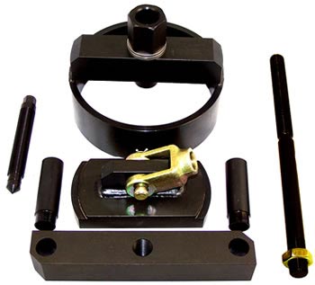
Why Impact Methods & Off-Center Pullers Cause Cut O-Rings & Head Gasket Failures
On Cummins NT and N14 heavy-duty engines, wet cylinder liners establish the critical combustion chamber sleeve and coolant jacket boundary. Because these 5.5" bore liners must seat flat against lower block ledges while sealing coolant with flexible rubber O-rings and crevice packing, maintaining parallel alignment during service is paramount. Technicians who attempt to extract stuck liners with improvised slide hammers or drive new liners down using wood blocks and brass mallets cause severe engine damage. Impact hammering twists the liner as it enters the lower block bore, pinching lower O-rings between the liner wall and sharp block chamfers. A sheared or cut O-ring allows engine coolant to leak directly into crankcase oil during engine warm-up. Furthermore, un-even liner seating leaves inconsistent liner protrusion across adjacent cylinders, preventing the cylinder head from sealing properly and causing repeated blown head gaskets. Utilizing the 24-pound M20105 Liner Puller & Press Combo eliminates these overhaul failures completely. The tool bridges across the top of the block deck, guiding a heavy threaded forcing rod straight along the bore center. During extraction, it lifts the liner smoothly up out of the block. During installation, it converts into a press plate, pushing the liner down in a continuous, smooth motion so O-rings compress evenly without shearing.
The 5-Step Cummins 5.5" Liner Service Protocol
- Position Puller Feet & Lower Shoe for Extraction: Lower the M20105 shoe assembly down through the 5.5" liner until the bottom plate hooks firmly beneath the lower liner lip. Support the upper bridge legs securely on the cylinder block deck.
- Advance Threaded Rod & Extract Seized Liner: Rotate the top forcing nut clockwise using a heavy socket or breaker bar. Mechanical screw force draws the liner straight up out of the block bore without cocking or scoring counterbores.
- Thoroughly Clean & Inspect Block Counterbores: Wire-brush and clean upper block counterbores and lower O-ring seal grooves. Inspect for cavitation erosion and verify counterbore ledges are clean and flat.
- Lubricate Fresh O-Rings & Position New Liner: Install fresh crevice packing and sealing O-rings into the lower liner grooves using vegetable oil or approved O-ring lubricant. Lower the new 5.5" liner squarely into the clean block bore.
- Convert M20105 to Press Mode & Seat Liner: Mount the M20105 press plate on top of the fresh liner flange. Advance the threaded forcing rod to push the liner down smoothly until it bottoms flush against the counterbore ledge. *Measure liner protrusion with a dial indicator to confirm factory spec before installing the cylinder head.*
PRO-TECH O-RING LUBRICATION & PROTRUSION CHECK MANDATE:
ALWAYS LUBRICATE LOWER O-RINGS with approved lubricant before pressing! Dry installation WILL shear seals against block chamfers! ALWAYS measure cylinder liner protrusion at four points using a dial depth gauge to guarantee head gasket sealing!
24.00 lbs High-Tensile Dual-Function Liner Service Master Kit. Protect Cummins Overhauls.
Get the M20105 Master Combo Now
overall rating:
my rating:
log in to rate