Step-by-Step Cylinder Head Removal: Professional Procedure Using ATC4919360 for Cummins ISX/X15
Step-by-Step Cylinder Head Removal: Professional Procedure Using ATC4919360 for Cummins ISX/X15
Professional technicians follow this exact procedure for safe, controlled cylinder head removal on Cummins ISX12, ISX15, and X15 engines. Complete guide with critical safety warnings.
Introduction: Professional Cylinder Head Removal
Cylinder head removal on Cummins ISX and X15 engines requires precision technique, proper tooling, and rigorous safety protocols. The difference between a successful head removal and a catastrophic failure often comes down to following exact procedures and respecting the 200+ pound weight of a complete cylinder head assembly.
Phase 1: Engine Preparation & Safety Protocol
- Allow complete engine cool-down – Minimum 6–8 hours since last operation. Never work on hot engines; severe burn hazard.
- Disconnect negative battery terminal – Prevents accidental starter engagement. Essential electrical safety.
- Drain all coolant from engine – Prevents spillage and contamination. Capture coolant for proper disposal.
- Depressurize fuel system – Release fuel system pressure per Cummins service manual. Safety critical.
- Disconnect all hoses and electrical connectors – Remove all connections to cylinder head (fuel, coolant, electrical, vacuum).
- Set up overhead crane or hoist – Position crane directly above engine centerline. Verify load capacity (minimum 1,000 lbs).
- Position work area – Ensure clear space below head for safe lowering. No personnel beneath lifting zone.
Phase 2: Cylinder Head Bolt Removal
- Remove cylinder head bolts in proper sequence – Follow OEM removal sequence (typically outer to inner, progressive)
- Use calibrated torque wrench for final bolts – Last 3-4 bolts removed under controlled torque to prevent sudden head movement.
- Document bolt locations and lengths – Cylinder head bolts vary in length. Mark each location for correct reinstallation.
- Inspect bolt holes in block – Check threads for damage. Note any stripped or damaged holes for repair.
- Place bolts in labeled container – Organize by location. Prevent mixing and incorrect reinstallation.
- Inspect gasket surface for contamination – Remove any gasket material or deposits from block surface.
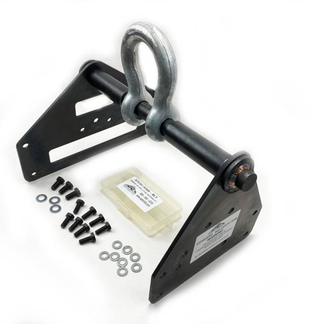
Phase 3: ATC4919360 Bracket Installation
- Inspect ATC4919360 bracket for damage – Check steel frame and mounting points for cracks or bending.
- Verify bracket mounting points align with head bolt holes – Symmetrical design should align perfectly with OEM pattern.
- Position bracket over cylinder head – Ensure mounting points engage directly with factory head bolt hole pattern.
- Install mounting fasteners through bracket into head – Use bolts or clamps per OEM specification. Tighten firmly.
- Verify bracket is secure and does not shift – Test by hand pressure. No movement permitted before lifting.
- Inspect pivoting lifting eye – Ensure pivot moves freely. No rust or corrosion affecting function.
- Attach sling or lifting device to bracket eye – Connect to overhead crane hook. Verify secure attachment.
Phase 4: Controlled Cylinder Head Lifting
- Take up slack in lifting sling slowly – Gradual tension ensures bracket is seated correctly before weight is applied.
- Test lift 2-3 inches off block surface – Stop lifting. Verify head lifts straight without tilting or shifting.
- If head tilts or shifts, lower immediately and recheck bracket seating – Never continue lifting with misalignment.
- Resume lifting slowly once proper alignment verified – Steady, controlled upward motion. No sudden jerking.
- Continue lifting to clear block surface – Lift approximately 12–18 inches to provide working clearance below head.
- Lower head to prepared work surface very slowly – Use blocking (wood, plastic) to prevent direct casting contact with surface.
- Remove lifting sling once head is fully supported on blocks – Verify head cannot shift or move on work surface.
⚠️ CRITICAL WARNING: Never step or work beneath lifted head. Never reach under head while suspended. Never modify lifting procedure. Always maintain minimum 6-foot clearance around lifting zone.
Phase 5: Head Inspection & Service
- Inspect cylinder head casting for cracks – Check around valve seats, between cylinders, water passages.
- Examine valve seat condition – Note any pitting, corrosion, or damage to valve seating surfaces.
- Inspect combustion chamber surfaces – Check for carbon deposits, erosion, or damage.
- Verify coolant passage integrity – Check for corrosion in cooling galleries. Document condition.
- Document all findings for service record – Detailed notes on head condition guide service decisions.
- Proceed with gasket surface cleaning, valve work, or head resurfacing as needed – Follow service plan based on inspection.
Phase 6: Head Reinstallation Using ATC4919360
- Prepare block surface for head reinstallation – Clean gasket surface thoroughly. Remove all debris and gasket material.
- Install new head gasket on block surface – Orient correctly per OEM specification. No shifting or tilting.
- Attach ATC4919360 lifting bracket to serviced cylinder head – Mount via same bolt holes used during removal.
- Connect lifting sling to bracket's pivoting eye – Verify secure attachment. No slippage.
- Lift head slowly to align over block deck – Slow movement allows precise positioning.
- Lower head carefully onto gasket – Gentle lowering prevents gasket shifting. Ensure head sits evenly on all sides.
- Once head is fully seated, remove lifting bracket – Unbolt bracket. Verify head remains in position.
- Install and hand-tighten all head bolts – Progressive hand tightening ensures even seating.
- Torque head bolts in OEM sequence to specification – Use calibrated torque wrench. Multiple passes may be required.
- Final torque verification – Check each bolt meets OEM specification. Document all readings.
- Reconnect all fuel, coolant, and electrical connections – Verify proper orientation and secure seating.
Phase 7: System Testing & Verification
- Refill coolant system to correct level – Use OEM-approved coolant. Follow fill procedure from service manual.
- Repressurize fuel system – Follow OEM procedure. Verify no fuel leaks around connections.
- Reconnect negative battery terminal – Restore electrical power to engine.
- Bleed coolant system if required – Follow OEM procedure to remove air from cooling passages.
- Start engine and monitor for leaks – Watch for coolant, fuel, or oil leaks around head.
- Allow engine to reach operating temperature – Verify normal thermostat operation. Check coolant level stability.
- Perform pressure test on cooling system – Verify no leaks at head gasket interface.
- Shut down engine and recheck all head bolt torque – Final verification after thermal cycling.
- Document complete service in engine records – Note all service performed, measurements, and test results.
Critical Safety & Quality Warnings
Never Commit These Mistakes:
- ❌ Never work on hot engine – Severe burn hazard. 6-8 hour cool-down minimum.
- ❌ Never lift head without ATC4919360 – Manual lifting risks dropping head and injury.
- ❌ Never use damaged bracket – Bent or cracked bracket fails during lift.
- ❌ Never skip bracket seating verification – Head must lift straight without tilting.
- ❌ Never position personnel under lifted head – Always maintain 6-foot clearance.
- ❌ Never exceed 750 lb lifting capacity – Bracket is rated for head assembly only, not engine.
- ❌ Never skip head bolt torque sequence – Improper sequence causes uneven gasket seating.
- ❌ Never skip final pressure testing – Test cooling system before releasing engine.
Frequently Asked Questions
Q: Can ATC4919360 be used for other Cummins engines?
A: No. This bracket is specifically designed for ISX12, ISX15, ISX, and X15 engine families. Other Cummins engines require different brackets.
Q: Can the bracket be used with any overhead crane?
A: Yes. The pivoting lifting eye accommodates standard 1/2" or 5/8" crane hooks. Verify crane capacity exceeds 1,000 lbs for safety margin.
Q: What is the rated lifting capacity?
A: 750 lbs maximum. This accommodates Cummins ISX/X15 cylinder head (200+ lbs) with significant safety margin.
Q: Can ATC4919360 be used to lift the entire engine?
A: Absolutely not. Bracket is designed exclusively for cylinder head lifting. Never attempt to lift engine block or complete engine with this bracket.
Safe Head Removal Protects Your Team
Get ATC4919360 – $450Key Takeaways
- ATC4919360 bracket is essential for safe Cummins ISX/X15 head removal
- Proper bracket installation prevents component damage and technician injury
- OEM-specification design ensures perfect bolt hole alignment
- 750 lb capacity handles full head assembly with safety margin
- Overhead crane attachment provides controlled, hands-free lifting
- Following exact procedure prevents $10,000–$250,000+ in damage/injury costs
- One prevented head failure justifies 22–555X the tool investment