Blog
Step-by-Step Fuel Rail Leak Testing: Professional Procedure Using ATC4919546 for Cummins ISX15/QSX15
Complete OEM-Compliant Fuel Rail Testing for Cummins ISX15/QSX15
Step-by-Step Fuel Rail Leak Testing: Professional Procedure Using ATC4919546 for Cummins ISX15/QSX15
Professional technicians follow this exact procedure for safe fuel rail pressure decay testing on Cummins ISX15 and QSX15 engines. Complete OEM-compliant guide using ATC4919546 block-off adapters for accurate leak source isolation.
Introduction: OEM-Compliant Fuel Rail Testing
Cummins ISX15 and QSX15 fuel rail pressure loss demands systematic, OEM-documented testing procedures. Improper diagnosis leads to $3,000–$8,600 in unnecessary parts replacement, technician safety hazards, and warranty issues. The ATC4919546 block-off adapter set enables the OEM-specified rail decay test procedure (Cummins TSB150104) that isolates the fault component without guesswork or fuel spray risk.
Phase 1: Pre-Test System Verification & Setup
- Document initial fuel rail pressure reading – Start engine and record steady-state rail pressure at idle (typical: 20,000–26,000 psi). Note any deviation from spec.
- Observe pressure decay over 30 seconds at idle – Typical decay: 0–500 psi (acceptable). Decay greater than 1,000 psi indicates leak (proceed to leak isolation).
- Turn engine off and allow 5-minute soak – Verify fuel pump shuts down. Listen for return flow noise. Record any unusual sounds.
- Connect fuel rail pressure gauge – Install OEM-compatible gauge at fuel rail test port (typically located on fuel rail itself).
- Locate all five injector fuel line connections – Identify and label all five ISX15/QSX15 fuel lines at the rail outlet. Take photos for reference.
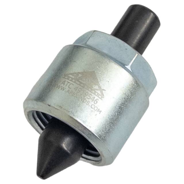
- Inspect ATC4919546 adapters for damage – Verify all five adapters are clean and undamaged before installation.
- Gather all tools and test equipment – Ensure pressure gauge, hoses, and wrenches are ready before beginning disconnection.
Phase 2: Fuel Line Disconnection & Adapter Installation
- Stop engine and allow cool-down (5–10 minutes) – Never disconnect high-pressure lines on running engine or hot fuel system.
- Place catch pan under fuel rail area – Capture residual fuel and prevent spill/contamination.
- Carefully disconnect first injector fuel line from rail outlet – Use proper wrench to prevent line damage. Residual pressure will release.
- Install ATC4919546 adapter into fuel rail outlet immediately – Hand-tighten firmly. This blocks off the first injector from the rail circuit.
- Repeat for all five injector fuel lines – Disconnect each line and install an adapter at the outlet. All five injector lines must be blocked off simultaneously for valid test.
- Verify all five adapters are installed and tight – Visual inspection confirms adapters are seated in all five fuel rail outlets.
- Wipe away any spilled fuel – Clean area ensures safe working environment.
Phase 3: Fuel Pump Activation & Initial Pressure Reading
- Turn ignition key to ON position (do not start engine) – Fuel pump activates for 2–3 seconds to pressurize fuel rail.
- Observe pressure gauge as pump pressurizes rail – Rail should climb to 20,000–26,000 psi (OEM spec). Note maximum pressure reached.
- Record initial maximum rail pressure – Write down exact psi reading at peak. This is baseline for decay test.
- Note exact time when pump shuts off – Pump typically stops after 2–3 seconds. Pressure should stabilize at maximum.
- Observe gauge continuously for next 10 minutes – With adapters blocking all five injectors, rail should hold pressure with zero decay (or minimal decay less than 500 psi per 10 minutes).
⚠️ CRITICAL TEST POINT: If rail pressure HOLDS steady (less than 500 psi loss over 10 minutes), the leak is NOT in the injectors or rail. Problem is in fuel pump, relief valve, or injector pump seal. If pressure DECAYS rapidly (over 1,000 psi loss), leak is likely in one or more injectors. Proceed to Phase 4 for injector isolation.
Phase 4: Injector-by-Injector Leak Isolation (If Needed)
- If Phase 3 showed rapid decay, proceed to injector isolation – Turn ignition OFF and allow 2-minute rest.
- Carefully remove ONE ATC4919546 adapter from the first fuel rail outlet – This reconnects that injector to the rail circuit. The other four injectors remain blocked off by their adapters.
- Turn ignition ON and pressurize rail again – Note pressure climb to maximum again.
- Observe pressure decay over 5 minutes with ONE injector connected – If pressure holds steady (less than 500 psi loss), that injector is NOT leaking. If pressure decays rapidly, that injector is leaking internally.
- Record result for first injector – Document PASS or FAIL.
- Install adapter back on first outlet and remove adapter from second outlet – Reconnect second injector for isolation test.
- Repeat test sequence for remaining four injectors – Isolate each injector individually. Document results: PASS (no leak) or FAIL (leaking).
- Identify all failed injectors – Any injector showing rapid decay needs replacement or reconditioning.
Phase 5: Fuel Rail Integrity Verification
- If all five injectors PASS (no internal leaks), rail must be tested with zero injectors connected – Turn ignition OFF.
- Verify all five ATC4919546 adapters are installed and tight in fuel rail outlets – All injectors must remain blocked off from rail.
- Turn ignition ON and pressurize rail – Pump pressurizes rail to maximum.
- Record maximum pressure and observe for 15 minutes with adapters blocking all injectors – If pressure holds at maximum with zero decay, fuel rail and pump are healthy.
- Pressure decay indicates fuel rail leak or relief valve fault – If decay occurs with all injectors blocked, internal rail leak or relief valve problem is present.
- Document fuel rail status – PASS (healthy) or FAIL (rail leak / relief valve fault).
Phase 6: Diagnostic Conclusion & Component Replacement Decision
- Analyze test results against OEM fault isolation tree – Cummins TSB150104 specifies which components to replace based on test results.
- If injectors FAILED: Replace identified leaking injectors only – Do not replace pump or rail unnecessarily.
- If rail/pump FAILED: Follow OEM replacement procedure for fuel system components – Pump or relief valve replacement may be required.
- Document all test pressures, decay rates, and findings – Complete diagnostic record required for warranty and future reference.
- Proceed with component replacement – Install only components identified by systematic testing.
Phase 7: Post-Replacement Verification & System Checkout
- Remove all five ATC4919546 adapters from fuel rail outlets – Carefully unscrew adapters and set aside safely.
- Reinstall original fuel lines at all five injector rail outlets – Verify all connections are tight. No leaks.
- Start engine and verify normal fuel pressure – Pressure should climb to OEM specification (20,000–26,000 psi) and remain steady.
- Observe pressure decay with engine running at idle – Typical decay: 0–500 psi (acceptable per OEM spec).
- Run engine for 5–10 minutes at various RPM – Verify stable pressure throughout operating range.
- Shut down engine and allow 5-minute soak – Observe residual pressure. Should hold at reasonable level.
- Document test results and component replacements in engine service record – Complete diagnostic history maintained.
Critical Safety & Diagnostic Warnings
Never Commit These Mistakes:
- ❌ Never disconnect fuel lines without blocking off adapters – 26,000+ psi fuel spray = severe burn hazard or fire risk.
- ❌ Never test with fewer than five adapters installed – All five injectors must be blocked off simultaneously for valid test.
- ❌ Never start engine with adapters installed – Adapters are for non-running test procedure only. Remove all adapters before engine start.
- ❌ Never replace components based on guess – Follow systematic test procedure. Replace only components identified by testing.
- ❌ Never skip fuel system priming after component replacement – Improper priming leaves air in rail = pressure issues.
- ❌ Never skip post-replacement pressure verification – Always confirm fuel system is healthy before returning vehicle to customer.
- ❌ Never work on high-pressure system without proper tools – Improvisation risks injury and misdiagnosis.
- ❌ Never skip safety documentation – Fuel system work must be fully recorded in service history.
Frequently Asked Questions
Q: What is acceptable fuel rail pressure decay per OEM specification?
A: Decay less than 500 psi over 10 minutes is acceptable. Decay greater than 1,000 psi indicates a leak requiring isolation and component replacement.
Q: Can this test procedure be used without ATC4919546 adapters?
A: No. Without adapters, fuel pressure cannot be properly isolated to individual components. Adapters are mandatory for OEM-compliant testing per TSB150104.
Q: Why are five adapters required instead of one or two?
A: ISX15/QSX15 rails have five injector outlets. All five must be blocked simultaneously to isolate the fuel pump, relief valve, and rail as a system. Testing with fewer adapters provides incomplete data.
Q: What if pressure loss is only on one injector?
A: Replace only that injector. The fuel pump, rail, and other four injectors are healthy. Systematic testing prevents $2,000–$5,000 in unnecessary parts replacement.
Accurate Fuel System Diagnosis Protects Your Business
Get 5-Adapter Set – $325Key Takeaways
- ATC4919546 adapters are essential for OEM-compliant ISX15/QSX15 fuel rail testing per TSB150104
- Proper procedure prevents $3,300–$8,600 in misdiagnosis-driven parts waste
- Five adapters block all injectors simultaneously for complete system isolation
overall rating:
my rating:
log in to rate