Blog
Step-by-Step Diesel Engine Liner Height & Counterbore Measurement: Professional Procedure Using ATC6434
Professional cylinder liner and counterbore measurement procedure for accurate diesel engine block preparation.
Professional technicians follow this exact procedure for accurate measurement of cylinder liner protrusion and counterbore depth using the ATC6434 universal liner height gauge. Proper measurement prevents head gasket failures and sealing issues.
Introduction: Accurate Liner Measurement is Non-Negotiable
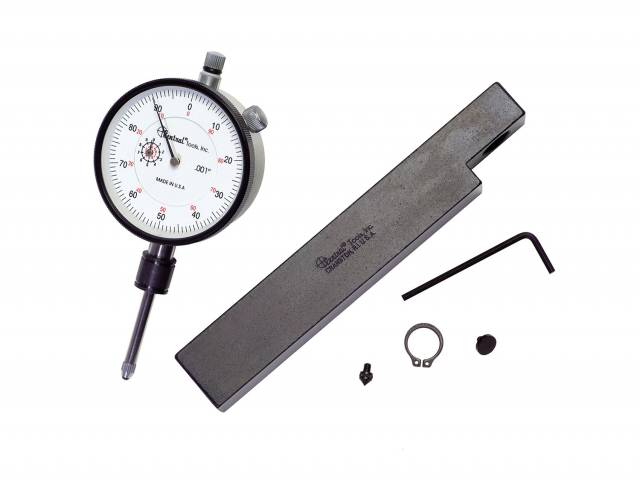
Cylinder liner protrusion (height above the deck surface) and counterbore ledge depth are two of the most critical dimensions in diesel engine block preparation. Tolerance on these measurements typically ranges from ±0.010" to ±0.030" depending on engine family. Errors in measurement or installation lead directly to head gasket failures, liner misalignment, and costly warranty claims. The ATC6434 universal liner height gauge provides the measurement precision needed to ensure these critical dimensions are within specification before engine assembly.
Phase 1: Tool Preparation & Block Setup
- Gather ATC6434 gauge and all interchangeable contacts – Verify pointed contact (for liner height) and flat contact (for counterbore depth) are clean and undamaged.
- Inspect deck surface of engine block – Ensure block is clean, free from machining debris, and that all liners are fully installed. No loose liners or partial installations.
- Verify block orientation – Block must be positioned horizontal with deck surface facing upward. Any tilt or angle introduces measurement error.
- Establish clean reference surface – Wipe deck area thoroughly with clean cloth. Remove any coolant, machining oil, or debris that could affect gauge contact.
- Confirm measurement location plan – Decide which cylinders will be measured (typically all cylinders, but at minimum measure #1, middle, and end cylinders for variation assessment).
Phase 2: Liner Height (Protrusion) Measurement
- Install pointed contact on ATC6434 gauge – The pointed tip will contact the top surface of the liner for precise protrusion measurement.
- Position sled base on clean deck surface – Sled must sit flat and stable on the block deck. Apply gentle downward pressure to ensure full sled contact across reference surface.
- Lower pointer contact until it touches the top of the first cylinder liner – The contact point should land on the center of the liner top surface, not on edges or shoulders.
- Read and record the gauge dial reading – Note the exact value shown on the dial. Typical liner protrusion specification: 0.010" to 0.030" above deck (varies by engine family—consult OEM specification).
- Lift gauge and move to next cylinder location – Reposition sled and pointer to measure second cylinder liner protrusion. Record result.
- Repeat for all cylinders – Measure protrusion on each cylinder and document results. Look for consistency across the block. Variation greater than 0.010" between cylinders indicates uneven deck machining or liner installation problems.
- Assess protrusion results – If any cylinder falls outside OEM specification (±0.010" to ±0.030" above deck):
- Protrusion too high: Liner may need to be re-seated or block deck re-machined
- Protrusion too low: Check for improper liner seating or counterbore ledge damage
- Variation between cylinders: Indicates uneven deck surface or liner installation quality issues
Phase 3: Counterbore Ledge Depth Measurement
- Replace pointed contact with flat contact – The flat surface will measure the depth of the counterbore ledge that supports the liner.
- Reposition sled base on clean deck surface – Same deck position as protrusion measurement. Sled must be stable and level.
- Lower flat contact until it touches the counterbore ledge shoulder – The flat contact surface should sit on the ledge surface (the step that supports the liner bore). This is the critical support surface for liner seating.
- Read and record the gauge dial reading – The dial now shows the depth of the counterbore ledge. Typical counterbore depth specification: 0.100" to 0.300" (varies significantly by engine—consult OEM specification and service manual).
- Assess counterbore depth results – Verify that ledge depth matches OEM specification:
- Ledge too shallow: Insufficient support for liner, causes tilting and wear
- Ledge too deep: May indicate over-machining, reduces bearing surface area
- Variations between cylinders: Indicates uneven counterbore machining or ledge damage
- Document counterbore depth for each cylinder – Record measurements and compare to specification. Note any out-of-spec dimensions.
⚠️ CRITICAL MEASUREMENT POINT: If counterbore ledge depth is out of specification, the block may require re-machining before liner installation. Improper ledge geometry compromises liner support and sealing integrity.
Phase 4: Data Analysis & Corrective Action
- Compile all measurement data – Create a spreadsheet or document listing every cylinder's protrusion and counterbore depth measurements against OEM specification.
- Assess variation across cylinders – Calculate the difference between highest and lowest readings. Variation greater than 0.010" indicates deck surface problems.
- Identify out-of-spec dimensions – Flag any cylinder where protrusion or counterbore depth exceeds specification limits.
- Determine root cause of problems – Possibilities include:
- Uneven deck machining surface
- Improper counterbore ledge machining
- Liner seating problems during installation
- Damaged or worn liners
- Block casting defects
- Execute corrective actions – Depending on findings:
- Deck surface correction: Re-machine to achieve uniform height and flat surface
- Counterbore correction: Re-machine ledges to proper depth specification
- Liner re-seating: Remove, clean bores, and re-install liners with proper seating force
- Liner replacement: If individual liners are damaged or defective
Phase 5: Final Verification & Documentation
- Re-measure all cylinders after corrective actions – Verify that protrusion and counterbore depth now fall within OEM specification.
- Confirm consistency across all cylinders – Maximum variation should be less than 0.010" between highest and lowest readings.
- Document final verification measurements – Create permanent record showing all cylinders meet OEM specification before engine assembly proceeds.
- Approve block for liner installation or engine assembly – Once all measurements verify, block is cleared for next assembly phase.
- Maintain measurement records with engine work order – Complete documentation is essential for warranty support and future service reference.
Critical Safety & Measurement Warnings
Never Commit These Mistakes:
- ❌ Never measure on a tilted or unsupported block – Block must be horizontal and stable. Angle introduces measurement error.
- ❌ Never measure with loose liners still in place – All liners must be fully seated. Loose liners give false protrusion readings.
- ❌ Never measure without cleaning the deck surface – Oil, debris, or machining chips affect gauge contact and skew readings.
- ❌ Never skip variation assessment across cylinders – Uneven deck geometry causes sealing failures. High variation is a red flag.
- ❌ Never ignore out-of-spec measurements – Proceed with assembly anyway, you're guaranteeing head gasket failure.
- ❌ Never measure only one or two cylinders – Every cylinder must be verified. Problems often affect only certain positions.
- ❌ Never use the wrong OEM specification – Confirm the exact spec from the service manual for your engine family.
- ❌ Never skip final re-verification after corrections – Always re-measure after re-machining or re-seating to confirm compliance.
Frequently Asked Questions
Q: What is typical liner protrusion specification on diesel engines?
A: Typical range is 0.010" to 0.030" above deck surface, but this varies significantly by engine family. Always consult the OEM service manual for exact specification. Incorrect specification reference will result in false out-of-spec determinations.
Q: What causes high variation in liner protrusion across cylinders?
A: Primary causes include uneven deck machining surface, improper liner seating during installation, or liner installation in the wrong order/position. Variation greater than 0.010" requires investigation and correction.
Q: What happens if counterbore ledge depth is incorrect?
A: Shallow ledge provides insufficient liner support, causing tilting and accelerated wear. Deep ledge may indicate over-machining and reduces bearing surface. Both scenarios compromise sealing integrity and durability.
Q: Can the ATC6434 be used on all diesel engine families?
A: The ATC6434 is a universal tool that accommodates a wide range of diesel blocks. However, always verify that the gauge will fit the specific block and liner bore configuration before use.
Accurate Liner Measurement Prevents Warranty Disasters
Get ATC6434 – $184.58Key Takeaways
- ATC6434 is essential for accurate diesel engine block preparation and liner installation
- Proper procedure prevents $14,000–$38,000 in head gasket failures and warranty disasters
- Liner protrusion and counterbore depth are two critical, independent measurements
- Variation assessment across cylinders identifies deck machining and seating problems
- Out-of-spec measurements require corrective action before engine assembly proceeds
- One prevented warranty failure justifies 76–206X the tool investment
- Permanent documentation of measurements is required for warranty support and traceability
overall rating:
my rating:
log in to rate