Blog
Step-by-Step International MaxxForce High-Pressure Fuel Rail Diagnostics: Using ATC ZTSE6098 Plugs
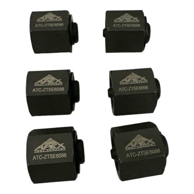
Professional fuel rail diagnostic testing procedure for International MaxxForce diesel engines.
Professional technicians follow this exact procedure for safe, accurate high-pressure fuel rail diagnostics on International MaxxForce diesel engines using the ATC ZTSE6098 plug set. Proper technique prevents fuel leakage, enables accurate pressure testing, and protects critical fuel system components.
Introduction: Professional Fuel Rail Diagnostics
International MaxxForce high-pressure fuel rail diagnostics require precision, safety, and proper equipment. Inaccurate sealing during testing leads to fuel leakage, contamination, and false fault codes that waste technician time and customer money. The ATC ZTSE6098 plug set provides the precision components needed; this procedure ensures they are used correctly to perform safe, accurate diagnostics that correctly identify fuel system faults.
Phase 1: Engine Shutdown & Fuel System Depressurization
- Shut down engine and allow to cool for 10–15 minutes – Hot fuel systems are dangerous. Cool engine reduces pressure and prevents steam/fuel vaporization during service.
- Open fuel filter/water separator and drain fuel if required – Depending on diagnostics, fuel system may need visual inspection for contamination or water presence.
- Locate fuel rail pressure relief valve or pressure test port – Most MaxxForce engines have dedicated test ports on the fuel rail. Consult service manual for exact location.
- Depress fuel system pressure release button (if equipped) – Some MaxxForce models have manual pressure release. Follow OEM procedure to safely bleed residual pressure.
- Prepare fuel collection container for residual fuel spillage – Small amount of fuel may spill when removing plugs. Use absorbent material under work area.
Phase 2: Access & Inspection of Fuel Rail Ports
- Remove engine cover or protective shroud as required for fuel rail access – Gain clear access to all fuel rail ports. Document cover removal for reassembly.
- Visually inspect fuel rail and all accessible ports – Look for leakage evidence, fuel saturation, or corrosion indicating previous failure. Photograph for technical records.
- Identify ports requiring plugging for pressure testing – Common ports: fuel supply inlet, return line, damper line, and secondary test ports. Consult service manual for specifications.
- Clean all fuel rail port threads with clean cloth – Remove fuel residue, dirt, or corrosion that could prevent proper plug seating or damage threads.
- Inspect ATC ZTSE6098 plugs for physical damage – Verify threads are clean and undamaged. Plugs must be in perfect condition for reliable sealing.
Phase 3: Fuel Rail Port Plugging & Pressure Testing Setup
- Identify which port is primary test point for fuel pressure gauge connection – This port will remain open for gauge connection. Other ports will be sealed with plugs.
- Carefully thread first ATC ZTSE6098 plug into non-test port – Hand-thread plug without forcing. If resistance encountered, stop immediately and verify thread alignment.
- Tighten plug to snug fit with appropriate wrench or socket – Do not over-tighten. Excessive torque damages threads or plugs. Snug fit (light pressure beyond hand-tight) is correct.
- Repeat plugging procedure for all ports except primary test point – Verify each plug is secure and shows no fuel seepage at threads. All other ports must be sealed.
- Connect fuel pressure gauge to primary test port – Use gauge appropriate for 25,000+ PSI operation. Ensure gauge connection is secure and won't slip during pressurization.
- Route gauge line to safe location away from engine hot spots – Pressure gauge must be readable and protected from accidental contact or heat damage.
Phase 4: Fuel Pressure Testing & Data Collection
- Start engine and allow to idle for 2–3 minutes – Engine warm-up stabilizes fuel pressure. Monitor gauge continuously during startup for abnormal pressure spikes.
- Record fuel pressure at idle (OEM specification typically 5,500–6,500 PSI for MaxxForce) – Consult specific engine service manual for exact idle pressure specification. Document actual reading.
- Gradually increase engine RPM to 1,500 and record pressure – Fuel pressure should increase proportionally with engine load. Note any pressure fluctuations or instability.
- Monitor pressure at 2,500 RPM for full-load specification (typically 25,000+ PSI) – Full-load pressure indicates fuel pump capacity and injector command pressure capability. Record value.
- Observe pressure stability across all RPM ranges – Look for sudden drops, spikes, or oscillations that indicate fuel delivery problems, damper issues, or control module faults.
- Return to idle and verify pressure returns to idle specification – Pressure should drop smoothly as load decreases. Inability to return to idle spec indicates regulator or pump problems.
- Compare measured pressures to OEM specification table – Determine if pressures are within acceptable range or indicate fuel system fault requiring component isolation.
Phase 5: Leak Isolation Testing (If Pressure Out-of-Specification)
- If pressure is low, isolate fuel supply line from pump to rail – Shut down engine, disconnect supply line from fuel rail port, and reconnect fuel pressure gauge directly to pump outlet.
- Start engine and test pump outlet pressure (bypass rail pressure regulator) – This isolates pump capability from regulator function. If pressure is normal here, regulator is faulty.
- If pressure is still low, fuel pump is defective – Proceed with fuel pump inspection or replacement. Record findings in technical record.
- For high-pressure conditions, check fuel regulator drain line return pressure – High pressure may indicate plugged drain line or regulator malfunction. Inspect drain for blockage.
- Test individual injector return lines for flow restriction – Disconnect each injector return line (one at a time) and verify fuel flows freely. Plugged returns cause back-pressure and high rail pressure.
- Document all leak isolation test results – Complete record of which component is causing out-of-specification pressure.
Phase 6: Fuel System Component Isolation & Service Planning
- Based on pressure test results, determine which component requires service or replacement – Options: fuel pump, regulator, injectors, filter, damper, or control module reprogramming.
- Plan component isolation procedure to confirm fault – For example, if injector pressure loss suspected, remove and plug one injector at a time to identify faulty unit.
- Remove and inspect suspected faulty component for visible damage or contamination – Photograph any damage before proceeding with replacement or service.
- Install replacement component using OEM specifications – Follow torque requirements and sealing procedures precisely. Use new fuel seals/O-rings as required.
- Prepare fuel system for repeat pressure testing – Use ATC ZTSE6098 plugs to seal rail ports again for post-repair verification testing.
Phase 7: Post-Repair Verification & Final Testing
- Re-plug fuel rail ports with ATC ZTSE6098 plugs (same procedure as Phase 3) – Ensure all connections are secure and show no fuel leakage.
- Connect fuel pressure gauge to primary test port – Use same gauge and location as initial testing for direct comparison.
- Start engine and run through same pressure test sequence as Phase 4 – Record idle, 1,500 RPM, and 2,500 RPM (full load) pressures.
- Compare post-repair pressures to OEM specification – All readings should now be within specification. Any remaining deviation requires further investigation.
- Verify pressure is stable across RPM ranges with no spikes or oscillations – Smooth, predictable pressure behavior indicates fuel system is operating normally.
- Shut down engine and verify no fuel leakage from plugged ports or gauge connection – All seals must be secure and dry. Any seepage indicates improper plug installation.
- Remove plugs, disconnect gauge, and inspect all ports for damage or leakage – Port threads should be undamaged and show no fuel residue indicating improper sealing.
Phase 8: System Reassembly & Documentation
- Reinstall original plugs in all fuel rail test ports – Use new OEM plugs (not diagnostic plugs) for final assembly. Secure and verify no leakage.
- Reconnect fuel filter/water separator drain if opened – Tighten to proper specification. Verify no fuel leaks at connection.
- Reinstall engine cover or protective shroud – Follow OEM fastener torque specification. Ensure all connections are secure.
- Document complete diagnostic and repair history – Record: initial pressure readings, fault identification, component replaced, post-repair pressures, and verification results.
- Create technical report for customer with pressure test results and explanation of fault and repair – Professional documentation demonstrates thoroughness and builds customer confidence.
Critical Safety & Procedure Warnings
Never Commit These Mistakes:
- ❌ Never test pressure on hot engine – High-pressure fuel systems can rupture or spray fuel at extreme pressure. Always cool engine 10–15 minutes before service.
- ❌ Never use incorrect plugs or fittings – Only ATC ZTSE6098 (or OEM ZTSE-6098) plugs rated for 25,000+ PSI. Improvised plugs fail under pressure.
- ❌ Never over-tighten plugs – Excessive torque damages rail threads or strips plug threads. Hand-tight + snug only.
- ❌ Never leave plugged ports unattended while engine running – Fuel leakage can occur suddenly. Continuously monitor for seepage.
- ❌ Never skip fuel rail pressure relief before service – Trapped pressure can be released suddenly, causing fuel spray and burns. Always depressurize first.
- ❌ Never use damaged plugs with stripped or corroded threads – Damaged plugs won't seal properly. Verify plug condition before use.
- ❌ Never mix diagnostic plugs with service plugs – Use ATC ZTSE6098 only for testing, not final assembly. Reinstall OEM plugs before returning to service.
- ❌ Never skip documentation of pressure readings – Complete records required for warranty support and technical troubleshooting history.
Frequently Asked Questions
Q: What is the correct idle fuel pressure for MaxxForce engines?
A: Typical MaxxForce idle pressure is 5,500–6,500 PSI, but this varies by engine year and configuration. Always consult the specific engine service manual for exact specification before determining if pressure is out-of-spec.
Q: Can ATC ZTSE6098 plugs be reused across multiple diagnostic cycles?
A: Yes, plugs are designed for repeated use across multiple vehicles and hundreds of test cycles. Inspect threads before each use and replace if damaged or corroded.
Q: What if fuel leaks from plugged port during testing?
A: Stop engine immediately. Shut down system and depressurize. Inspect plug threads for damage and verify proper tightness. If leakage persists, replace plug with new one and retry.
Q: Are ATC ZTSE6098 plugs compatible with all MaxxForce engine years?
A: ATC ZTSE6098 is OEM-equivalent to ZTSE-6098 and is compatible with MaxxForce 11, 13, 15, N13, A26, and other models
overall rating:
my rating:
log in to rate