
Blog
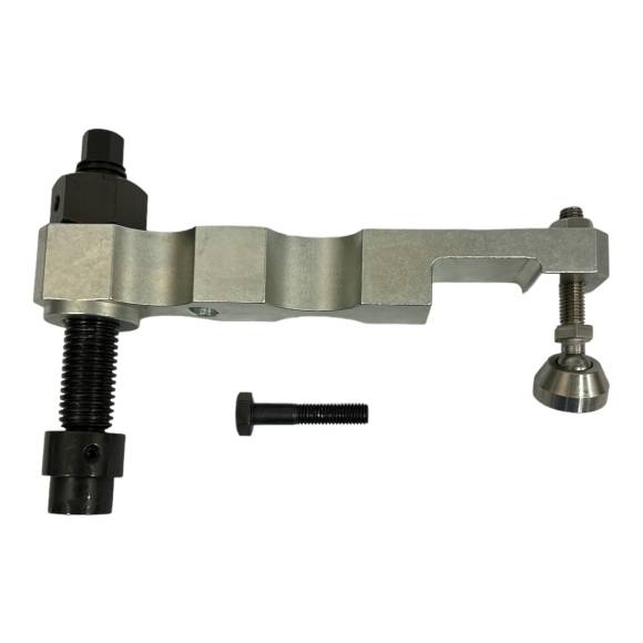
Cummins ISX15 / QSX15 Fuel Injector Sleeve Ring Installation with the ATC 5394735
Six cylinders, six installations, zero comebacks.

A complete shop-floor procedure for installing the injector sleeve expansion ring on Cummins ISX15, QSX15, and X15 CM2250 / CM2350 platforms — written for the technician who has to make the seal hold the first time.
Why Sleeve Ring Installation Is Non-Negotiable
The fuel injector sleeve expansion ring on a Cummins ISX15, QSX15, or X15 engine is not a serviceable item that can be "checked and reused." Once disturbed, it must be replaced. The expansion ring is a mechanical interference seal — it depends on a precisely controlled deformation cycle to create a metal-on-metal coolant-tight barrier between the injector pocket and the coolant gallery. Reusing a deformed ring, installing a new ring with the wrong tool, or attempting an improvised pull-up will guarantee one of three outcomes: immediate coolant intrusion on first start, slow-progressing seepage that destroys the engine over the next 1,500 hours, or fuel contamination of the cooling system at peak operating pressure.
The ATC 5394735 Fuel Injector Sleeve Ring Installer exists to make this procedure repeatable, fast, and warranty-safe. This guide walks the entire operation from bench preparation through final torque check.
🔧 PRO-TIP: Always Bench-Set Before You Pull Up
Before you put the installer plate against the sleeve, dry-fit the entire 5394735 kit on the bench with the new ring in place. Verify the installer component (5395005) bottoms evenly against the ring without rocking. A rocking installer means you've got debris in the bore or a damaged sleeve — fix it before you swage anything, because once the ring is expanded, you don't get a second chance.
Pre-Procedure Diagnostics: What to Check Before You Pick Up the Tool
Before the ATC 5394735 touches the cylinder head, the head itself must pass a full diagnostic gate. Skipping this stage is the single most common reason for repeat failures, even when the installation tool is used correctly. Start with a visual deck-surface inspection under bright shop lighting — look for any cracks radiating from the injector bores, between the bore and the nearest coolant passage, or between adjacent bores. Cracks in this region are catastrophic and condemn the head. Next, pull a precision straightedge across the deck face in both diagonals and along all four edges. Any gap greater than 0.003 inch with a feeler gauge means the head is warped beyond service limits and must be machined or replaced before a new sleeve install will hold.
Inspect each injector bore individually with a borescope. You're looking for three specific failure indicators: cavitation pitting on the lower sleeve land (caused by long-term coolant erosion), residual carbon deposits at the sleeve-to-deck interface, and any evidence of prior sealant or RTV use. Cavitation pitting deeper than 0.005 inch means the lower land is no longer a viable sealing surface — the head needs machine-shop attention or replacement. Carbon residue cleans up with approved solvent and a soft brass brush, but anything that's been hot-welded to the casting requires careful mechanical removal without scoring the parent material. Any sign of prior RTV indicates a previous improvised repair — these heads almost always need professional remediation before a new sleeve install will succeed.
Then move to the new sleeves themselves. Even factory-fresh sleeves can arrive with shipping damage. Inspect each new sleeve under magnification: any dent, scratch, or out-of-round condition on the lower sealing land disqualifies the sleeve from service. Verify your expansion rings are the correct part number for your engine variant — Cummins has revised ring specifications across CM2250 and CM2350 platform updates, and using a superseded ring on a current-production engine will create a seal that holds for hours instead of years. Confirm with your parts supplier that the ring batch matches the latest engineering revision before you commit to the install.
Finally, verify shop environment conditions. Ambient temperature should be stable between 60°F and 80°F. Humidity should be moderate — high humidity introduces moisture into the sealing interface, while extremely dry conditions can attract airborne particulate that contaminates the bore. The bench surface should be flat, clean, and dedicated — running the ATC 5394735 procedure on a cluttered general-purpose bench is asking for a tipped installer plate or a dropped fastener at the worst possible moment. Stage every tool, every component, and every consumable before the head leaves its protective cover.
The Sleeve Ring Installation Checklist
- Step 1: Prepare the Cylinder Head and Inspect the Injector Sleeves. With the head removed and on the bench, thoroughly clean each injector bore using approved solvent and lint-free wipes. The lower sealing surface where the new expansion ring will seat must be free of carbon, varnish, old sealant residue, and machining swarf. Use a borescope to inspect the sleeve walls for scoring, pitting, or cavitation damage from coolant erosion. Any sleeve showing wall pitting deeper than 0.005 inch must be replaced — the ring won't seal against a compromised sleeve regardless of installer accuracy. Confirm the new injector sleeves are seated to spec and that the lower sealing land is dry, clean, and ready to accept the expansion ring. Have your kit components staged: installer plates 5394731 and 5394732, socket head cap screw 3910497, hex head cap screw 3946377, plain washer 3968031, roll pin 5394946, heavy hex nut 5394947, and installer component 5395005. Lay them out on a clean tray in installation order.
- Step 2: Position the New Expansion Ring on the Sleeve. Take a new factory-spec expansion ring (these are supplied separately by your Cummins parts source — the ATC 5394735 is the installation tool, not the ring itself). Inspect the ring under bright light for any nicks, burrs, or out-of-round deformation. A damaged ring is a guaranteed leak — discard and replace. Place the ring squarely on the lower land of the injector sleeve, ensuring it sits flat and concentric. Many technicians use a light, oil-soluble assembly lubricant on the outer face of the ring to ease initial swage — verify your engine builder's approved lubricant list before doing so. Do not use grease, anti-seize, or RTV — any of these will contaminate the sealing surface or carbon-up under combustion temperatures and cause premature seal failure.
- Step 3: Set Up the ATC 5394735 Installer Assembly. Place installer plate 5394731 across the top of the cylinder head, aligning the plate's relief over the target injector bore. Install installer plate 5394732 on the underside of the head, positioned directly below the injector sleeve, capturing the expansion ring location. Pass the socket head cap screw 3910497 through the upper plate, down through the bore, and engage it with the heavy hex nut 5394947 on the lower side. Add the plain washer 3968031 in its specified position to distribute clamping load. Insert the installer component 5395005 — this is the precision-machined swage element that contacts the expansion ring during pull-up. The roll pin 5394946 indexes the installer to prevent rotation under load. Hand-tight the assembly first to confirm all components are correctly nested before applying torque. If anything binds, stop and re-stage — never force the installer.
- Step 4: Execute the Pull-Up Sequence. Using a calibrated torque wrench, apply load to the hex head cap screw 3946377 in a smooth, continuous motion. Follow your engine manufacturer's documented torque-to-yield specification for the expansion ring pull-up — never improvise this value. The ATC 5394735 transfers your applied torque into a precise axial swage force on the expansion ring, deforming it against the sleeve land and creating the coolant-tight seal. The pull-up motion should be steady and smooth — any jerking, slipping, or change in resistance feel indicates a problem (debris, misalignment, ring damage). Stop immediately if anything feels wrong. Once the specified torque is achieved, hold for the documented dwell time (typically 3–5 seconds), then release. Back the cap screw out smoothly and lift the installer assembly clear of the head.
- Step 5: Inspect, Document, and Verify the Seal. With the installer removed, visually inspect the expansion ring. The ring should sit fully seated against the sleeve land with no visible gap, no extruded material, and uniform contact all the way around the circumference. Use a borescope to verify the ring's outer face is seated cleanly — a tilted or partially seated ring is an immediate failure signal. Document the install in the engine build sheet: date, technician, torque value applied, sleeve serial number if tracked. Some shops perform a pressure leak-down test on the assembled head before reinstall — if your facility has this capability, use it. A leak-down at this stage costs nothing; a leak-down on a fully assembled engine costs days. Repeat steps 2 through 5 for each remaining injector position. Six cylinders, six installations, six verifications — no shortcuts.
Troubleshooting Common Issues
Symptom 1: Installer plate rocks or won't sit flat. The cylinder head deck surface or the upper sealing land is contaminated. Pull the installer, re-clean both surfaces with solvent, dry thoroughly with shop air, and re-seat. If rocking persists, inspect the head deck for warpage with a precision straightedge and feeler gauge — a warped head won't seal regardless of ring install quality and must be machined or replaced.
Symptom 2: Cap screw binds before reaching torque spec. Either the threads are dirty/damaged, the installer assembly is misaligned, or a foreign object is trapped in the sleeve. Disassemble the ATC 5394735 stack, inspect each component thread, and re-clean the bore. Never force a binding fastener — you'll deform the installer plate or strip the threads, ruining the tool.
Symptom 3: Ring shows uneven seating after install. The ring was either off-center at start, the installer component (5395005) is worn, or the pull-up was applied unevenly. Remove and discard the deformed ring, inspect the 5395005 component for swage-face wear, and re-execute the procedure with a new ring. If the 5395005 shows visible wear, contact Apex for component-level replacement — don't run a worn swage element.
Symptom 4: Coolant leak on first engine start after rebuild. Most likely a contaminated sealing surface at install or a damaged ring. Pull the head, inspect each ring, identify the leaker, and re-execute. This is the single most common warranty claim on ISX15/QSX15 rebuilds — and the single most preventable when the ATC 5394735 is used correctly.
Symptom 5: Hex nut 5394947 spinning without clamping. The threads on the cap screw or nut are stripped, or the lower installer plate isn't properly captured against the head. Stop the procedure, disassemble, inspect the threads on both 3910497 and 5394947, and replace any damaged hardware. The ATC 5394735 kit includes complete hardware — if a component is compromised, contact Apex for kit-level support.
Tool Compatibility & Engine Variations
The ATC 5394735 is engineered for the complete Cummins 15-liter family running CM2250 and CM2350 engine control modules:
- ISX15 CM2250 — On-highway truck applications, pre-SN and SN configurations
- ISX15 CM2350 X101 — Updated EPA-compliant configurations
- QSX15 CM2250 PowerGen — Standby and prime power generator drive
- QSX15 CM2250 ECF — Electronic-controlled fuel platform
- QSX15 CM2250 X115 — Industrial and off-highway applications
- QSX15 CM2350 X105 / X106 — Updated industrial control variants
- X15 CM2350 X114B / X116B — Current-production on-highway and industrial
If your engine's nameplate matches any of the above, the ATC 5394735 is the correct tool. For engines outside this family (ISX 11.9, ISX12, ISL9, ISB6.7), use the appropriate platform-specific installer — contact Apex Tool Company at 812-579-5478 for cross-reference assistance.
Safety & Shop Best Practices
Eye protection is mandatory. Expansion ring swaging involves significant clamping force. A failed installer component or stripped fastener can release that energy violently. ANSI Z87.1 safety glasses minimum, full face shield preferred.
Use a calibrated torque wrench. Pull-up torque on this procedure is non-negotiable. A "good enough" pull-up isn't good enough — under-torque means an unsealed ring, over-torque means a deformed sleeve. Verify your torque wrench calibration before starting and again at scheduled intervals.
Work clean. Every surface the ring contacts must be surgically clean. Wipe the bore, wipe the ring, wipe the installer face, then wipe again. Carbon, sealant residue, and machining swarf are the silent killers of injector sleeve seals.
Don't reuse rings. A removed expansion ring is a scrap ring. Period. The mechanical deformation that creates the seal is single-use by design.
Document every install. Engine build sheets, torque logs, technician initials, ring lot numbers if available. When a warranty claim arrives 18 months later, your documentation is your defense.
Technician FAQ
Q: Do I need any consumables beyond the ATC 5394735 kit?
You'll need new factory-spec expansion rings (one per cylinder), approved assembly lubricant, lint-free wipes, and solvent. The ATC 5394735 supplies all reusable tooling components.
Q: Can the kit hardware (cap screws, nut, washer) be replaced if it gets damaged?
Yes — contact Apex Tool Company at 812-579-5478 for individual component-level replacement. Each piece (3910497, 3946377, 3968031, 5394731, 5394732, 5394946, 5394947, 5395005) is identified by part number.
Q: What torque value do I apply during pull-up?
Always reference your current Cummins service manual for the engine variant you're working on. Torque values can change between revisions and between engine families — never use a "remembered" value from a previous job.
Q: How do I know when the swage is complete?
The torque wrench achieving the documented specification value, combined with the documented dwell time, completes the swage. Visual inspection after disassembly confirms uniform ring seating.
Q: My installer plate has a slight burr on the edge — is it still usable?
A burr on a non-functional edge is cosmetic. A burr on a sealing-contact face or a thread face is not. Inspect carefully and contact Apex if you're unsure — running a damaged installer face will deform the ring.
Q: Can I use the ATC 5394735 on a head that's still installed in the engine?
The procedure is designed for bench operation. In-engine use is not supported and would compromise alignment, cleanliness, and safety.
Q: How do I store the tool between uses?
Clean each component thoroughly after use, apply a light coat of corrosion-inhibiting oil, and store in a sealed case. Avoid humid environments — the precision-machined surfaces deserve climate-controlled storage.
Q: How does ATC's version compare to the Cummins OEM tool?
Functionally identical. Same dimensions, same hardware kit, same procedure — at a fraction of the OEM tooling cost.
Get the ATC 5394735 on Your Bench. Make the Seal Hold the First Time.
$255.00 — In Stock. Free shipping on orders over $500 (US continental).
Phone: 812-579-5478 / 800-365-2233 | Mon–Fri 8 a.m.–5 p.m. ET
overall rating:
my rating:
log in to rate