Blog
Tech Guide: Caterpillar Cylinder Liner Height & Protrusion Auditing
Precision lower-block structural reconditioning guidelines for freight fleets.

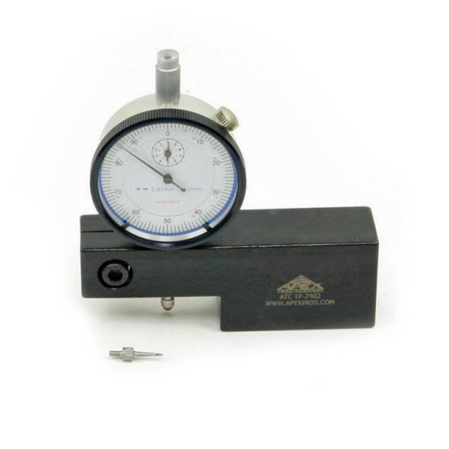
Prepping a mid-frame heavy engine block for final assembly or installing fresh shims? Learn the professional technical sequence to calibrate and check deck heights using the ATC 1P-2402 metric gauge.
Why Loose Counterbore Audits Lead to Catastrophic Compression Loss
The structural lip of a Caterpillar cylinder liner sits inside a precision-machined counterbore shelf at the top of the engine block. Under continuous heavy engine stroke pounding, that cast shelf can experience micro-settling or wear, pushing the liner deeper into the block casting. If a line technician drops a cylinder head down over an unverified liner that lacks proper protrusion height, the combustion fire ring on the head gasket will fail to compress completely. The intense injection heat will blast right past the weak seal area, scorching the block face and mixing hot exhaust straight into the oil and coolant jackets. Utilizing a dedicated parallel sled gauge like the ATC 1P-2402 provides absolute surface verification, ensuring you select the perfect shim adjustment to establish uniform fire-ring load metrics across all cylinders.
The 5-Step Liner Height Auditing Protocol
- Deck and Flange Chamber Cleaning: Clean the engine block deck face and the internal liner counterbore ridges aggressively with solvent. Ensure there is absolutely no old gasket grit, carbon crust, or rust scale present, as any surface particle will distort your fine micro-metric readouts.
- Zero the 1P-2402 Sled Gauge: Place the flat bottom base of the ATC 1P-2402 sled tool squarely onto a perfectly flat, clean section of the engine block surface deck next to the cylinder opening. Press down firmly and loosen the indicator lock nut to zero out your metric dial face.
- Secure the Cylinder Liner Hold-Down: Drop your target liner into the block port cavity (with or without shims as specified). Thread and torque down temporary factory liner hold-down bolts to press the sleeve firmly down into its counterbore seat, mimicking final cylinder head torque conditions.
- Map the Relative Protrusion Grid: Carefully slide the zeroed ATC 1P-2402 sled across the deck surface until the indicator tip drops onto the highest top lip edge of the cylinder liner ring. Record the metric reading. Take measurements at four separate points around the circumference of the ring to track any un-parallel tilt patterns.
- Calculate Shimming and Verify Fit: Compare your recorded variance grid against the engine manual specs. If the protrusion measurements fall short of factory limits, pull the liner and install precise matching shims beneath the lip. Re-test the height with the gauge to verify a flat, uniform profile before final head placement.
PRO-TECH DIAL CALIBRATION SECURITY MANDATE:
Always double-check your dial zero index point every single time you move to a fresh cylinder liner well! Even tiny changes in workspace temperatures or small vibrations on the tool cart can shift the fine dial calibration hair slightly off-target. Keeping your base zero reference validated stops frustrating tracking calculation mistakes across the block deck.
Concentric Depth Balancing. Stop Compression Leaks in the Bay.
Get Your Caterpillar 1P-2402 Sled Gauge
overall rating:
my rating:
log in to rate