Blog
Tech Guide: Adjusting Cummins Injector Heights Flawlessly
Precision top-end fuel injection timing guidelines for fleet service mechanics.

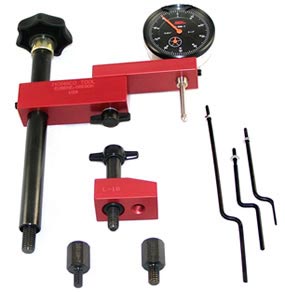
Running a top-end overhead service on a Cummins N14 or M11? Learn the professional technical sequence for setting injector plunger travel precisely using the M20120-A fixture.
Why Rigid Fixture Alignment Prevents Camshaft Damage
On Cummins engines utilizing mechanical rocker-driven fuel systems, injector plunger depth governs when and how violently fuel enters the combustion chamber. If an injector is set too deep, the rocker arm exerts excessive mechanical force on the injector body, risking micro-fractures in the plunger or crushing the camshaft lobe. If it is set too shallow, ignition retards, leading to unburnt fuel tracking out the tailpipe. Attempting to anchor a dial indicator using generic magnetic bases is highly prone to subtle flexing, introducing measurement errors. Utilizing an application-targeted fixture like the M20120-A forces the indicator tool to track perfectly square and uniform, ensuring spot-on adjustments.
The 5-Step Overhead Adjustment Sequence
- Perform Valve Set Bar Alignment: Bar the engine over manually until the target cylinder timing marks on the accessory drive pull line match the service manual alignment specifications. Ensure the cylinder is on the compression stroke with both intake and exhaust valves completely closed.
- Anchor the M20120-A Fixture: Clean the top surface of the rocker housing land cleanly. Mount the M20120-A structural steel fixture firmly onto the rocker box deck using the designated mounting locations. Hand-torque down the locking screws to guarantee zero fixture deflection.
- Zero the Dial Indicator Profile: Insert your precision dial indicator dial through the guided channel on the M20120-A arm. Position the indicator tip so it rests flatly centered on the top shoulder of the injector plunger assembly. Pre-load the dial indicator smoothly and zero out the outer bezel track.
- Execute Plunger Travel Tracking: Follow your specific Cummins engine service guidelines to back off or advance the injector rocker arm adjusting screw. Slowly cycle the adjustment until the indicator needle confirms the precise vertical plunger travel dimensions required for your specific timing code.
- Lock and Verify the Setting: Secure the injector adjusting screw locknut to factory torque specs while holding the screw stationary. Remove the M20120-A fixture assembly, move to the next firing order cylinder index, and replicate the sequence to lock in total top-end alignment.
CRITICAL ADJUSTMENT INSIGHT:
Always ensure the engine block block casting is completely cooled down to ambient temperature before executing a precision injector or valve overhead tune-up. Attempting to index settings on a warm engine introduces thermal expansion variations that can skew your final plunger depth measurements by several thousandths of an inch.
Precision Overhead Tune-Ups. Command Quality Operations.
Order the Cummins M20120-A Fixture
overall rating:
my rating:
log in to rate