
Blog
Cummins NT & NTC 855 Accessory Drive Pulley Removal Steps
Precision front-end maintenance guidelines for heavy diesel rebuilders and fleet mechanics.
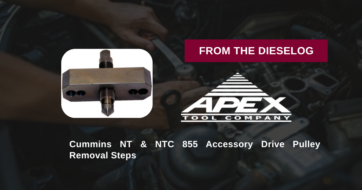
Removing a seized or press-fit accessory drive pulley during a front gear cover service, air compressor overhaul, or engine teardown on a Cummins NT/NTC 855 engine? Follow this step-by-step professional workshop procedure to set up the M20010 bolt-on puller plate, protect the shaft end, apply controlled forcing screw torque, and extract pulleys smoothly without damage.

Why Improvised Jaw Pullers Cause Cracked Pulleys & Bent Shafts
On Cummins 855 CID engines, the front accessory drive pulley powers vital gear-driven systems. Because these pulleys sit under high interference press-fits, extracting them requires dedicated tooling. Technicians who attempt removal using universal jaw pullers or pry bars quickly encounter failure. Hooking jaw puller legs under the outer cast iron pulley rim concentrates immense bending forces on the cast metal lip. As tension builds, the brittle casting snaps or deforms, ruining the pulley belt grooves. Even worse, off-center jaw loading cocks the pulley on the shaft taper, galling the precision steel shaft snout and destroying internal housing bearings. Utilizing the 2-pound M20010 specialty puller tool completely eliminates these removal hazards. Threading high-tensile mounting bolts directly into the pulley’s internal hub holes anchors the heavy steel bridge plate flush against the face. When the central forcing screw is advanced, it pushes directly against the center of the shaft, pulling the pulley straight off its taper with zero side loading or rim deformation.
The 5-Step Cummins NT/NTC 855 Accessory Drive Pulley Extraction Protocol
- Clean Pulley Hub & Threaded Mounting Holes: Remove drive belts and the central shaft retaining bolt. Clean the front face of the accessory drive pulley and thread holes thoroughly using solvent and a wire brush to clear rust scale and debris.
- Position M20010 Puller Plate & Thread Mounting Bolts: Place the M20010 puller bridge plate squarely against the pulley face. Align the tool slots with the factory-threaded holes on the pulley hub. Thread high-tensile mounting cap screws through the tool into the hub until fully engaged.
- Align Central Forcing Screw with Shaft Centerline: Thread the central forcing screw into the M20010 bridge plate until its hardened point seats firmly into the center dimple of the accessory drive shaft snout. *Verify the tool plate sits perfectly parallel to the pulley face.*
- Apply Penetrating Oil & Advance Forcing Screw: Apply clean engine oil or anti-seize compound to the forcing screw threads. Using a manual socket wrench, advance the forcing screw clockwise. The steady, centered axial force will break the press-fit bond and draw the pulley off the shaft smoothly.
- Remove Tool & Inspect Component Surfaces: Unbolt the M20010 tool from the extracted pulley. Inspect the accessory drive shaft snout and keyway for burrs or scoring. Clean shaft surfaces and verify front cover oil seal integrity before installing fresh components.
PRO-TECH FORCING SCREW LUBRICATION & MANUAL WRENCH MANDATE:
ALWAYS LUBRICATE FORCING SCREW THREADS with heavy oil or anti-seize before applying high torque! Dry threads bind and damage tool threads! ALWAYS advance forcing screws using MANUAL HAND TOOLS; never use pneumatic impact wrenches, which can shock-crack cast iron pulley hubs!
2 lbs Precision Structural Tool Steel Extraction Tool. Protect Cummins 855 Overhauls.
Get the M20010 Pulley Puller Now
overall rating:
my rating:
log in to rate