
Blog
Tech Guide: Engine Block Counterbore Sleeving & Machining Steps
Precision block machining guidelines for engine remanufacturers and diesel machine shops.
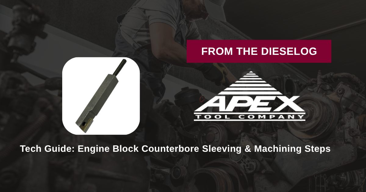
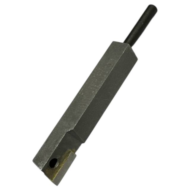
Preparing a fretted or damaged heavy-duty diesel engine block for press-fit counterbore repair sleeves? Follow this step-by-step professional workshop procedure to set up your PT-2050-D / M52050 machining system, install the PT-2000-109 carbide cutting bit, adjust feed rates, and machine perfectly flat counterbore ledges.
Why Dull Cutting Bits Cause Cracked Cylinder Liners & Head Gasket Blowouts
On heavy-duty wet and dry sleeve diesel engines, maintaining uniform counterbore seating depth is critical. When combustion pressures fire inside the cylinder, the liner flange relies on a 100% flat, perpendicular counterbore ledge to resist clamping deformation. When engine rebuilders use worn, dull, or inferior steel cutter bits during counterbore sleeving operations, the tool rubs against the cast iron rather than shearing it cleanly. This friction generates localized thermal expansion, causing tool chatter waves, micro-tapering, and uneven ledge depth around the bore perimeter. Installing a repair sleeve onto a chattered or tapered ledge creates localized stress points underneath the sleeve. When the cylinder head is torqued down, this uneven support causes the cylinder liner to flex or crack along the top flange, leading to blown head gaskets, coolant-in-oil contamination, and total engine seizure. Utilizing the fresh, sharp carbide PT-2000-109 cutter bit completely eliminates machining defects. Its precision-ground tungsten carbide cutting edge shears tough cast iron with minimal feed pressure, establishing a smooth, dead-flat surface that ensures complete surface contact for repair sleeves and liner seats.
The 5-Step Engine Block Counterbore Machining Protocol
- Clean & Inspect Engine Block Deck & Bore: Remove the old liner and clean the block deck surface and counterbore region thoroughly using solvent. *Verify the deck is clean and free of burrs to allow stable machining tool mounting.*
- Install PT-2000-109 Carbide Bit into PT-2050-D Tool Holder: Insert the PT-2000-109 cutter bit firmly into the cutter holder of your PT-2050-D or M52050 counterbore machining unit. Tighten the locking set screw securely to eliminate bit movement.
- Mount & Center Machining Unit over Cylinder Bore: Position the PT-2050-D unit over the target cylinder bore. Align and lock the tool base securely to the engine block deck using the recommended hold-down hardware. *Ensure 100% concentric centering relative to the cylinder bore axis.*
- Set Depth Micro-Adjuster & Begin Machining Cut: Zero the depth micrometer on the clean counterbore ledge. Advance the tool feed in light, controlled increments per pass. Turn the cutter unit smoothly by hand or power drive to machine the counterbore wall and seating ledge until reaching sleeve specification depth.
- Inspect Machined Ledge & Verify Sleeve Fitment: Vacuum away cast iron chips and wipe the counterbore clean. Inspect the machined ledge with a depth micrometer and straightedge across 360 degrees to verify a dead-flat, smooth finish before pressing in the repair sleeve.
PRO-TECH FEED RATE & CHIP CLEARANCE MANDATE:
ALWAYS MAINTAIN CONSTANT, MODERATE FEED PRESSURE during cutting passes to prevent carbide edge rubbing! ALWAYS clear cast iron chips frequently with a vacuum or compressed air—never allow accumulated chips to recut and score the fresh seating ledge!
1.00 lb Premium Carbide Counterbore Cutting Bit. Protect Engine Block Overhauls.
Get the PT-2000-109 Bit Now
overall rating:
my rating:
log in to rate