
Blog
Tech Guide: Cummins NT855 & N14 Front Main Seal & Wear Sleeve Extraction & Seating Steps
Precision front-end maintenance guidelines for commercial fleet and Class 8 mechanics.
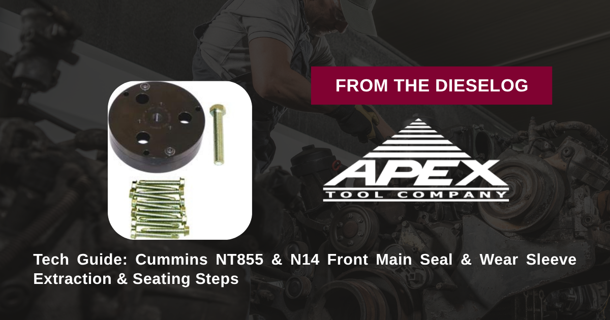
Extracting a seized front seal/wear sleeve and pressing fresh replacements during an overhaul on a Cummins NT855, NH, or N14 engine? Follow this step-by-step professional workshop procedure to set up the M20110-C puller plate, remove worn components cleanly, apply retaining compound, and press fresh sleeves and seals to exact OEM depth.

Why Improvised Removal & Driver Methods Cause Fatal Front Cover Damage
On Cummins N14 and 855 CID engines, replacing front crankshaft main seals requires extra care due to the tight interference fit of the inner wear sleeve. Over years of high-temperature operation, engine heat and oil varnish bake the wear sleeve tightly onto the steel crankshaft snout. Technicians who attempt removal using cold chisels, pry bars, or torch heat risk gouging the precision crankshaft nose or warping the front gear cover face. Deep scratches on the crankshaft snout allow crankcase oil to weep underneath new wear sleeves, resulting in chronic front main leaks. Furthermore, driving new wear sleeves on using sockets or hammer drifts cocks the thin metal wall, creating microscopic waves along the sealing track that shred new elastomeric seal lips instantly. Utilizing the 5-pound M20110-C master kit completely eliminates these service hazards. The kit's extraction plate bolts directly to the component, drawing the old sleeve and seal off along a 100% straight axial path without touching the crankshaft snout. For reassembly, the installer plate anchors to the front crankshaft nose threads, drawing the new sleeve and seal into place with smooth, parallel mechanical force until exact OEM depth is achieved.
The 5-Step Cummins N14/NT855 Front Main Seal & Sleeve Protocol
- Mount M20110-C Removal Assembly & Extract Worn Components: Remove the front damper. Thread the M20110-C extractor plate into the old seal/wear sleeve assembly. Turn the central forcing screw clockwise to pull the worn seal and wear sleeve straight off the crankshaft snout cleanly.
- Clean & Inspect Crankshaft Snout Surface: Clean the front crankshaft snout thoroughly using solvent and fine Scotch-Brite to remove old sealant, rust scale, and dirt. *Verify the steel snout is 100% smooth, clean, and free of metal burrs.*
- Apply Retaining Compound to Crankshaft Nose: Apply a light, uniform film of high-temperature anaerobic retaining compound (such as Loctite 609/680) to the crankshaft snout OD to prevent oil weeping underneath the new wear sleeve ID.
- Position Components & Mount M20110-C Installer Assembly: Position the fresh wear sleeve and front main oil seal over the crankshaft snout entrance chamfer. Place the M20110-C installer plate over the assembly and thread forcing bolts into the crankshaft nose threads until hand-tight.
- Press Components to Factory Depth Stop & Inspect: Apply clean engine oil to forcing bolt threads. Turn forcing bolts evenly using a manual wrench to draw the new wear sleeve and seal squarely onto the snout until the tool plate bottoms against the factory depth stop. Remove the tool, wipe away excess compound, and inspect 360 degrees for flat, un-distorted seating.
PRO-TECH RETAINING COMPOUND & MANUAL WRENCH MANDATE:
ALWAYS APPLY ANAEROBIC RETAINING COMPOUND to prevent oil migration underneath the wear sleeve ID! ALWAYS advance installer forcing screws using MANUAL HAND TOOLS; never use pneumatic impact wrenches, which can shock-distort micro-thin wear sleeves!
5 lbs Precision Structural Tool Steel Dual-Function Kit. Protect Cummins 14L Overhauls.
Get the M20110-C Service Kit Now
overall rating:
my rating:
log in to rate