
Blog
Tech Guide: Cummins C8.3 & ISL Front Crankshaft Wear Sleeve Installation Steps
Precision front-end maintenance guidelines for commercial fleet and vocational truck mechanics.
Renewing a grooved front crankshaft snout during a front main seal replacement or in-frame overhaul on a Cummins C8.3 or ISL engine? Follow this step-by-step professional workshop procedure to clean the crankshaft snout, set up the M20135-A piloted installer, press the wear sleeve on smoothly, and seat fresh front oil seals to factory depth.
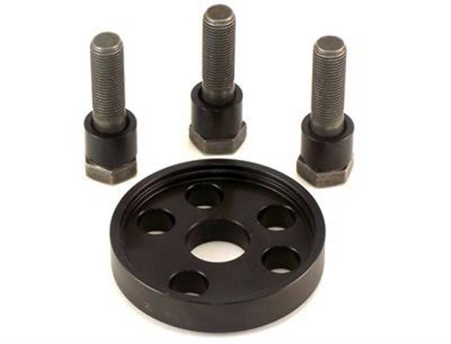
Why Improvised Pipe Sections Destroy Micro-Thin Crankshaft Wear Sleeves
On Cummins C Series and ISL engines, front crankshaft wear sleeves are precision-stamped from micro-thin stainless steel to provide a renewed, ungrooved surface for the front main seal lip. Because these sleeves feature an interference fit over the crankshaft snout, they must be pressed on with absolute parallel alignment. When technicians attempt to drive wear sleeves on using improvised steel pipe sections or hammers, the impact force is never distributed evenly across the sleeve face. The pipe edge cocks the sleeve on the snout entrance chamfer, buckling the thin metal wall or flaring the outer oil retainer flange. Once a wear sleeve flares or distorts during installation, it loses its perfect cylindrical shape. Installing a new front main seal over a distorted sleeve causes instant seal lip destruction, slinging engine oil across the front accessory drive within minutes of operation. Utilizing the 3-pound M20135-A piloted installer tool completely eliminates these costly installation errors. By threading the central stud directly into the front crankshaft nose, the tool’s contoured drive cup engages 100% of the sleeve perimeter simultaneously. Turning the drive nut draws the sleeve onto the snout smoothly and evenly, stopping automatically when exact factory depth is achieved.
The 5-Step Cummins Front Crankshaft Wear Sleeve Installation Protocol
- Clean & Inspect Crankshaft Snout: Remove the old front seal and damper. Clean the front crankshaft snout thoroughly using solvent and fine emery cloth to remove rust scale, dirt, and burrs. *Inspect the snout surface and verify it is free of sharp raised metal edges.*
- Apply Retaining Compound & Position Sleeve: Apply a light, uniform coat of recommended anaerobic retaining compound (such as Loctite 609/680) to the inner diameter of the new wear sleeve or crankshaft snout surface. Position the wear sleeve squarely over the front entrance chamfer of the crankshaft snout.
- Mount M20135-A Installer Tool Assembly: Position the M20135-A drive cup over the wear sleeve. Thread the central forcing stud into the threaded holes on the nose of the crankshaft until fully seated.
- Press Wear Sleeve to Factory Depth Stop: Apply clean engine oil to the forcing stud threads. Turn the central forcing nut clockwise using a manual socket wrench. The M20135-A drive cup will press the wear sleeve smoothly over the snout until the cup bottoms firmly against the crankshaft shoulder stop.
- Remove Tool & Inspect Installed Sleeve: Unthread and remove the M20135-A tool assembly. Wipe away excess retaining compound. Inspect the installed wear sleeve 360 degrees to verify it is seated perfectly square, flat, and un-marred without edge flaring. Proceed with front main oil seal installation per Cummins OEM factory manual guidelines.
PRO-TECH RETAINING COMPOUND & MANUAL WRENCH MANDATE:
ALWAYS APPLY ANAEROBIC RETAINING COMPOUND to prevent oil migration underneath the wear sleeve ID! Always advance the forcing nut using MANUAL HAND TOOLS; never use pneumatic impact wrenches, which can shock-distort micro-thin wear sleeves!
3 lbs Precision Structural Tool Steel Service Assembly. Protect Cummins Front Main Seals.
Get the M20135-A Wear Sleeve Installer Now
overall rating:
my rating:
log in to rate