Blog
Professional Cylinder Head Removal & Installation: Complete Workflow Using ATC88800188-174
Cylinder Head Removal Workflow | Volvo & Mack Complete Guide
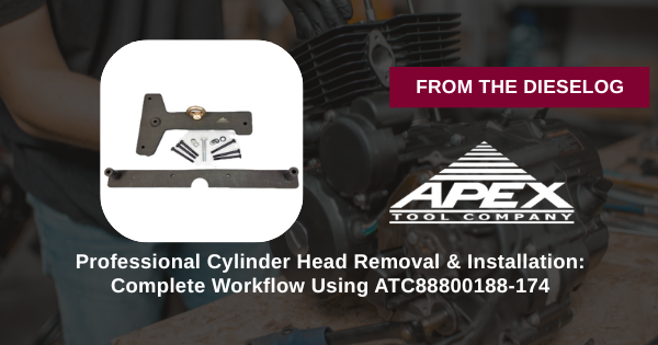
Professional Cylinder Head Removal & Installation: Complete Workflow Using ATC88800188-174
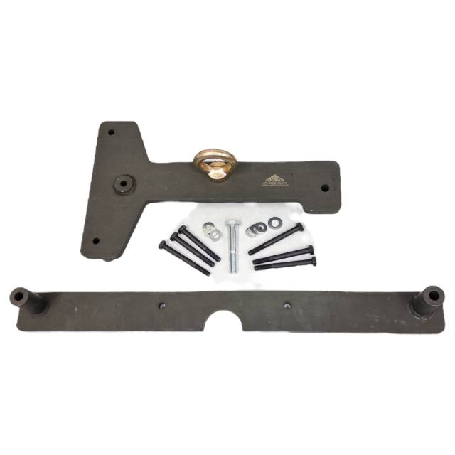
Cylinder head removal and installation on Volvo D12, D13, D16 and Mack MP8, MP10 engines requires precision, proper equipment, and adherence to manufacturer procedures. This complete workflow guide covers the ATC88800188-174 Cylinder Head Lifting Bracket with Extension Kit for professional heavy-duty diesel shops. From pre-removal inspection through final torque verification, follow these steps for damage-free, professional-grade head service every time—protecting both the component and your shop's profitability.
GET LIFTING BRACKET NOW
Complete Workflow Coverage • Extension Kit Included
Phase 1: Pre-Removal Inspection & Preparation
- Drain cooling system – Complete coolant removal to prevent spills and contamination.
- Disconnect electrical harness – Remove injector connectors, sensor leads, and engine control modules.
- Remove intake manifold – Follow OEM torque sequence in reverse; store hardware in labeled containers.
- Remove exhaust manifold – Disconnect turbo if equipped; follow OEM procedures.
- Clean head area – Remove dirt, oil, and debris from around cylinder head perimeter.
- Document bolt positions – Photo record head bolts and stud layout for reinstallation reference.
Phase 2: Head Bolt Removal & ATC88800188-174 Setup
- Remove head bolts in OEM sequence – Follow cross-pattern sequence to prevent warping.
- Store bolts organized – Keep bolts from each stud position together for reinstallation.
- Inspect OEM lifting points – Locate designated head lifting lugs on casting.
- Verify ATC88800188-174 compatibility – Confirm lifting bracket engagement points match head type.
- Attach lifting bracket securely – Ensure lifting lugs are fully engaged (no loose fit).
- Adjust extension assembly – Set extension height for truck model (VN/VHD/VT/VAH/CHU/CXU/GU/TD/LEU/LR/MRU).
Phase 3: Safe Cylinder Head Extraction
- Connect engine hoist to lifting bracket – Use hoist with load capacity ≥ 2X cylinder head weight.
- Remove jack stands and support blocks – Head must be free-hanging from hoist only.
- Take up slack in hoist chain – Verify even tension across all attachment points.
- Lift slowly and smoothly – No jerking or sudden movements; 2-3 inches per minute.
- Monitor for binding – Stop immediately if head binds on block or gasket material.
- Apply penetrating oil if needed – Allow 15-30 minutes; resume slow lifting.
- Lift head clear of block – Keep head level and parallel to block throughout extraction.
- Lower head onto work surface – Gently rest head on wooden blocks; never drop or rotate roughly.
Professional Head Handling = Zero Damage
ORDER ATC88800188-174 NOW →Phase 4: Block Inspection & Surface Preparation
- Inspect deck surface – Check for warping, cracks, or damage from previous removal.
- Remove old gasket material – Scrape carefully using soft scraper (never steel); avoid deep scratching.
- Clean deck thoroughly – Use brake cleaner to remove all oil, coolant, and debris.
- Measure deck flatness – Use straightedge to verify within OEM specifications.
- Check stud condition – Inspect for bent, cracked, or corroded studs requiring replacement.
- Clean all stud threads – Remove corrosion and old sealant to ensure proper torque reading.
Phase 5: Cylinder Head Reinstallation
- Inspect head surfaces – Check for cracks, warping, or damage on mating surface.
- Install new head gasket – Position gasket per OEM orientation (firing side up/down).
- Position head using lifting bracket – Lower head carefully using ATC88800188-174 assembly.
- Verify gasket alignment – Confirm gasket stays in position (use gasket sealant if OEM approved).
- Install head bolts hand-tight – Thread all bolts by hand before torquing.
- Torque bolts to OEM specification – Follow prescribed sequence in multiple passes (typically 25%, 50%, 75%, final).
- Allow settling time – Wait 15 minutes; retorque final pass to specification.
- Reconnect all components – Reinstall manifolds, harnesses, and sensors.
Every Cylinder Head Service Needs Professional Equipment
ADD TO CART • ATC88800188-174Critical Warnings: Avoid These Mistakes
- ❌ NEVER use chains or ropes without bracket – Uneven pressure cracks head
- ❌ NEVER lift with side clamps – Damages casting surfaces permanently
- ❌ NEVER jerk or rotate during extraction – Breaks gasket seal and studs
- ❌ NEVER skip deck cleaning – Debris causes gasket failure and coolant leaks
- ❌ NEVER skip stud inspection – Bent studs prevent proper torque and bolt stretch
- ❌ NEVER deviate from OEM torque sequence – Improper sequence warps head
- ❌ NEVER reuse old head gaskets – Old gaskets cannot reseal
- ❌ NEVER skip final retorque – Bolts relax after settling; must be re-torqued
Professional Head Service = Reliable Engines
The Head Lifting Tool Every Heavy-Duty Shop Needs
BUY ATC88800188-174 NOW → $645
✅ Volvo D12/D13/D16 • Mack MP8/MP10
✅ Adjustable Extension • 11 Truck Models
✅ Professional-Grade • 100% Damage Prevention
✅ Adjustable Extension • 11 Truck Models
✅ Professional-Grade • 100% Damage Prevention
overall rating:
my rating:
log in to rate