Blog
Step-by-Step Detroit Diesel 60 Series Top Deck Sleeve Cutting: Professional Procedure Using M30146
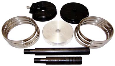
Professional top-deck liner seat machining and sleeve installation procedure for Detroit Diesel 60 Series engines.
.png)
Professional technicians follow this exact procedure for accurate top-deck liner seat restoration on Detroit Diesel 60 Series engines using the M30146 sleeve cutting tool kit. Proper technique prevents head gasket failures and ensures reliable sealing.
Introduction: Professional Top Deck Restoration
Detroit Diesel 60 Series top-deck liner seat restoration is a precision procedure that requires accurate tooling, proper technique, and careful attention to geometry. Improper execution leads to sealing failures, liner misalignment, and catastrophic warranty issues. The M30146 kit provides the precision components needed; this procedure ensures they are used correctly to restore deck integrity and prevent future sealing problems.
Phase 1: Block Preparation & Damage Assessment
- Remove engine block from machine or workbench mount – Position for safe access to top deck. Ensure block is stable and secure before beginning machining work.
- Visually inspect all top-deck liner seats – Look for corrosion, tapering, dimensional loss, or previous damage. Photograph problem areas for documentation.
- Clean entire top-deck surface with wire brush and solvent – Remove all corrosion, scale, oil, and machining debris. Exposed metal shows true damage extent.
- Measure counterbore depth on each cylinder – Document which cylinders need repair and severity of wear. Standard DD60 counterbore: 0.3514–0.3533 inches, variation <0.0015 inches.
- Identify cylindersrequiring sleeve installation – Mark out-of-spec or severely damaged counterbores that need M30146 sleeve/bushing restoration.
- Gather M30146 kit components – Verify cutter plate, bit, guide plate, alignment plate, guide rod, and six inserts (bushings) are present and undamaged.
Phase 2: PT-2050 Tooling Setup & Alignment
- Mount M30146 kit components onto PT-2050 / PT-2050-D base – Follow OEM instructions for port-tool setup. Ensure all fasteners are tight and components seated fully.
- Position guide plate and alignment plate on first cylinder – Plates must sit perpendicular to deck surface. Any tilt introduces angular error in cutting.
- Install guide rod through alignment fixture – Rod provides centering reference for cutter bit to ensure perpendicular machining on liner seat.
- Verify perpendicularity with level or precision square – Check multiple points around guide rod. Maximum allowable deviation: 0.005 inches per inch of height.
- Secure block and tooling against inadvertent movement – Use clamps or fixed mounting. Vibration during cutting causes chatter and poor surface finish.
Phase 3: Top-Deck Sleeve Cutting Operation
- Apply cutting fluid to cutter bit – Use appropriate coolant for machining cast iron. Coolant reduces friction, dissipates heat, and improves surface finish quality.
- Engage cutting bit with worn counterbore surface – Lower bit gradually until it contacts existing counterbore material. Begin at slow speed (500–1,000 RPM for cast iron).
- Monitor cutting action continuously – Listen for chatter or binding. If cutting becomes rough, stop immediately and verify alignment. Chatter indicates misalignment or insufficient coolant.
- Feed cutter bit through full depth of counterbore – Bit will machine away damaged material and create new cylindrical surface for sleeve installation. Maintain steady, consistent feed pressure.
- Complete cutting pass and remove cutter bit from bore – Raise bit fully before moving to next cylinder. Do not leave bit positioned in bore when not cutting.
- Inspect newly machined counterbore surface – Surface should be smooth, cylindrical, and free from chatter marks. If poor finish observed, verify alignment and repeat on another test bore before proceeding.
Phase 4: Repeat for All Damaged Cylinders
- Reposition guide and alignment plates on next cylinder – Verify perpendicularity again. Do not assume alignment carries over from previous cylinder—each cylinder must be verified independently.
- Repeat cutting operation for each damaged counterbore – M30146 kit includes inserts for all six cylinders, but only machine those that need restoration. Do not over-machine healthy counterbores.
- Maintain consistent cutting parameters across all cylinders – Same coolant, same speed, same feed pressure ensures uniform finished surface quality and proper sleeve seating.
- Document which cylinders received sleeve cutting – Record cylinder numbers, original damage description, and new surface condition for warranty and traceability purposes.
Phase 5: Repair Sleeve / Bushing Installation
- Clean newly machined counterbore bores with solvent and air – Remove all machining chips and coolant residue. Clean bore is essential for proper sleeve seating.
- Inspect ATC-8065 STD inserts (bushings) included in M30146 kit – Verify they are clean and undamaged. Inserts must seat perfectly in newly machined bores.
- Apply press assembly if required for sleeve installation – Follow OEM procedure for insertion of repair sleeves into newly machined counterbores. Sleeves must be pressed in perpendicular to deck surface.
- Verify installed sleeves are fully seated and flush with deck surface – Sleeves should not protrude or sit recessed. Improper seating compromises liner flange contact.
- Check that arrow marks on installed sleeves align with coolant holes – Detroit Diesel 60 Series sleeves have alignment marks that must line up with block cooling passages for thermal management.
Phase 6: Verification & Quality Inspection
- Measure counterbore depth on each restored cylinder – New depth should be within OEM specification (0.3514–0.3533 inches for DD60). Variation between adjacent cylinders <0.001 inches.
- Verify machined surface finish with visual inspection and tactile check – Surface should be smooth without chatter marks. Run finger lightly across surface—should feel uniform with no rough spots.
- Confirm installed sleeves provide clean sealing surface – Sleeves must be undamaged and flush. Imperfect sleeves compromise liner flange sealing and must be replaced.
- Test fit new cylinder liners into restored counterbores – Liners should seat smoothly without rocking or lateral movement. Check liner protrusion specification (0.000–0.003 inches with <0.002 inch variation).
- Document all measurements and inspection results – Complete documentation required for warranty compliance and future service reference. Photograph final deck geometry if possible.
Critical Safety & Procedure Warnings
Never Commit These Mistakes:
- ❌ Never machine without verifying perpendicularity – Angular cutting creates tapered counterbores that fail to seat liners properly. Always verify alignment on every cylinder.
- ❌ Never skip cutting fluid application – Dry cutting produces chatter, poor surface finish, and shortened cutter bit life. Always use appropriate coolant.
- ❌ Never over-machine healthy counterbores – Machine only damaged cylinders requiring restoration. Over-machining removes material unnecessary and weakens support structure.
- ❌ Never install sleeves without proper cleanliness – Machining chips in bore prevent full seating of repair sleeves. Always clean bores thoroughly before sleeve installation.
- ❌ Never skip verification measurements after machining – Verify counterbore depth and finish quality immediately. Discover problems before proceeding to liner installation.
- ❌ Never forget sleeve alignment arrow marks – Marks must align with coolant holes for proper thermal management. Misalignment causes cooling performance degradation.
- ❌ Never skip final liner fit verification – Test fit new liners to confirm proper seating. Improper seating indicates machining or sleeve installation problems requiring correction.
- ❌ Never skip documentation of work performed – Complete records required for warranty support and future service history. Undocumented work complicates future diagnostics.
Frequently Asked Questions
Q: What if some cylinders don't need repair sleeves?
A: Machine only cylinders with out-of-spec counterbore depth or visible damage. Healthy counterbores should not be machined. M30146 includes inserts for all six cylinders, but install only where needed.
Q: Can M30146 be used on DD60 engines other than 12.7L/14L?
A: The M30146 is specifically designed for DD60 Series (12.7L/14L). Different engine platforms may require different tools. Always confirm engine designation before beginning work.
Q: What if cutter bit produces poor surface finish or chatter?
A: STOP immediately. Check alignment perpendicularity, verify adequate cutting fluid application, and inspect cutter bit for damage. Do not continue with poor surface finish—it will compromise sleeve seating and liner support.
Q: How do I know if counterbore depth is within specification?
A: Standard DD60 counterbore depth: 0.3514–0.3533 inches. Variation between cylinders must be <0.001 inches. Use precision depth gauge or dial indicator to measure. Always consult OEM service manual for your specific engine.
Restore Decks. Ensure Sealing. Protect Engines.
Get M30146 – $1,184.53Key Takeaways
- M30146 is essential for professional Detroit Diesel 60 Series top-deck restoration
- Proper procedure prevents $12,000–$35,000 in warranty failures and block scrap costs
- Each cylinder must be verified for perpendicularity independently
- Cutting fluid and proper machining speed ensure clean surface finish
- Repair sleeves must be installed flush with deck surface and properly aligned
- Verification measurements confirm spec compliance before final assembly
- One successful restoration with M30146 saves 10–29X the kit investment vs. block replacement
overall rating:
my rating:
log in to rate