Blog
Tech Guide: Detroit Diesel Series 60 Cylinder Liner Installation with the J-35597
A complete shop-floor procedure for Series 60 wet liner installation — done right the first time.

A complete shop-floor procedure for installing Series 60 wet liners correctly the first time — with torque references, common pitfalls, and the specific role the J-35597 plays at every step.
Why Proper Liner Installation is Non-Negotiable
The Detroit Diesel Series 60 uses a wet cylinder liner design — meaning coolant flows directly against the outer wall of the liner, separated from the crankcase only by two precision O-rings at the lower seal land. This architecture delivers excellent thermal management and serviceability, but it leaves zero margin for installation error. A liner that goes in tilted, with rolled O-rings, or with uneven seating force becomes a slow-motion failure waiting for thermal cycling to expose it. Every Series 60 liner that gets installed wrong eventually becomes a head-off repair, a coolant-contaminated bottom end, or both. The J-35597 exists because Detroit Diesel engineers concluded — correctly — that this operation cannot be done reliably by hand or by improvisation.
Beyond the mechanical risk, there's a compliance dimension. Documented service procedures specify the J-35597 by part number. Insurance carriers, warranty programs, and OEM dealer agreements increasingly require that documented service tools be present and used. A shop running Series 60 rebuilds without the J-35597 is one warranty audit away from a difficult conversation.
The Series 60 Liner Installation Checklist
- Step 1 — Block Preparation and Counterbore Verification.
Before any liner touches the block, confirm the cylinder counterbores are clean, undamaged, and within service spec. Use a dial bore gauge to measure counterbore depth around four points per bore. Detroit Diesel publishes specific depth tolerances in the service literature — verify each bore individually. Tools needed: dial bore gauge, depth micrometer, lint-free shop towels, clean solvent. Common mistakes here are skipping the counterbore inspection and assuming the previous liner left the bore in spec — coolant erosion and cavitation can change counterbore geometry over a service life. If any counterbore is out of spec, the block must be machined or sleeved before proceeding. Do not improvise with shims. - Step 2 — Liner Inspection and O-Ring Preparation.
Unbox the new liner and inspect the outer wall for shipping damage, the O-ring grooves for sharp edges or burrs, and the liner ID for any contamination. Install new O-rings — never reuse — and lubricate them per Detroit Diesel's specified lubricant (typically a clean engine oil or specified assembly lube). Tools needed: clean nitrile gloves, OEM-spec assembly lube, soft pick for O-ring seating. Common mistakes: using grease or sealant on O-rings (causes swelling and incorrect seating force), installing O-rings dry (causes shearing on entry), and stretching O-rings during installation (causes asymmetric seating). - Step 3 — Dry-Fit Verification (No O-Rings).
Before final installation, perform a dry fit of the liner without O-rings to confirm the bore is clean and the liner drops freely to the counterbore shoulder. Measure liner protrusion with a precision protrusion gauge — Series 60 spec is typically referenced in service literature in the range commonly published by Detroit Diesel. If protrusion is out of spec at dry fit, do not proceed. Investigate the counterbore depth or liner flange dimension. Tools needed: protrusion gauge, straightedge, feeler gauge. Common mistake: skipping dry fit because the technician trusts the parts. New liners can be out of spec from the factory; dry fit is your final verification. - Step 4 — Final Installation with the J-35597.
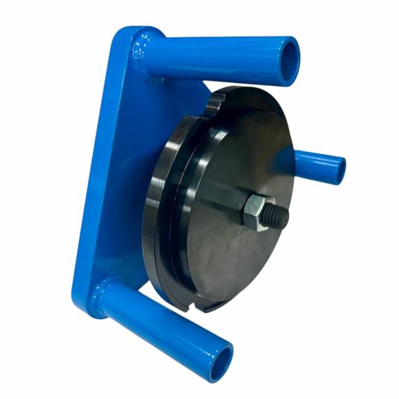
With O-rings installed and lubricated, position the liner squarely above the bore. Engage the J-35597 installation tool on the upper liner flange according to the tool's design — the tool centers force on the axial centerline of the liner and provides a reaction surface that cannot tilt. Apply controlled, even pressure to drive the liner down past the lower O-rings and into the counterbore until fully seated. Tools needed: J-35597, clean rags, torque or pressure reference per service literature. Common mistakes: using the J-35597 with damaged or contaminated mating surfaces (transfers irregularities to the liner), striking the J-35597 with a hammer (it is a press-style tool, not a strike tool), and rushing past the O-ring engagement zone (the moment of greatest seal damage risk requires steady, controlled motion). - Step 5 — Post-Install Protrusion Verification and Documentation.
With the liner fully seated, re-measure protrusion at four points per bore using the protrusion gauge. Confirm all readings fall within Detroit Diesel's published specification and that the variation across the four points is within tolerance. Document each cylinder's protrusion reading on the rebuild traveler. Tools needed: protrusion gauge, feeler gauge, traveler/job documentation. Common mistakes: measuring protrusion at only one or two points (asymmetric seating won't be caught), failing to document readings (kills warranty claims), and accepting "close enough" readings on the edge of spec (Series 60 head gaskets are unforgiving of marginal protrusion).
🔧 PRO TIP — The "Four Quarters" Protrusion Method
Always measure liner protrusion at the 12, 3, 6, and 9 o'clock positions on every bore. If the maximum minus the minimum reading exceeds Detroit Diesel's variation spec, the liner is seated unevenly — pull it, inspect the counterbore and O-rings, and reinstall. A single reading at one point will hide the exact failure mode the J-35597 is designed to prevent.
Troubleshooting Common Issues
Symptom 1 — Liner Will Not Seat to Counterbore Shoulder. If the liner stops short of full seating, the most common causes are debris in the counterbore, an O-ring that has rolled or pinched on entry, or a counterbore depth that has been altered by previous machining. Pull the liner immediately. Do not increase force. Inspect the counterbore floor with a borescope or mirror, replace O-rings, and reinstall. Forcing a liner that won't seat is the fastest way to destroy a block.
Symptom 2 — Excessive or Uneven Liner Protrusion After Install. Excessive protrusion indicates either the counterbore is too shallow (block needs machining) or there is debris under the liner flange. Uneven protrusion across the four measurement points indicates the liner is tilted — possibly from an O-ring rolled in its groove, or from contamination on one side of the counterbore. Pull, clean, replace O-rings, reinstall with the J-35597, and re-measure.
Symptom 3 — Visible O-Ring Damage After Removal. If a removed liner shows cuts, rolls, or pinches on the O-rings, the most common root causes are dry installation (insufficient lube), sharp edges in the counterbore chamfer, or installation force applied off-axis. The J-35597 eliminates the off-axis cause; chamfer condition and lubrication are technician-controlled.
Symptom 4 — Coolant in Oil After Initial Run-Up. Almost always traces back to a damaged lower O-ring. Pull the head, pull the liner, and inspect. Document the failure mode for warranty and process improvement. This is the exact failure profile the J-35597 prevents when used correctly with proper O-ring prep.
Symptom 5 — Premature Liner Wear or Out-of-Round. When a Series 60 returns with rapid liner wear after a rebuild, suspect installation distortion. A liner pressed in tilted will run out-of-round under combustion load and consume rings prematurely. The J-35597's axial force geometry directly prevents this failure mode.
Tool Compatibility & Series 60 Variations
The J-35597 is engineered for the Detroit Diesel Series 60 engine family. The Series 60 line includes the 11.1L, 12.7L, and 14.0L displacement variants, all of which share common cylinder liner architecture and counterbore geometry. The tool is appropriate for on-highway truck applications, marine variants, generator-set installations, and industrial Series 60 power packs. It is not intended for non-Series 60 engines — DDC two-cycle engines (6V-92, 8V-92, etc.) use a fundamentally different liner design and require different service tooling. Always confirm the engine family before tool selection.
Safety & Shop Best Practices
Liner installation involves heavy parts, precision force, and overhead positioning — treat it as a two-person operation when the engine is on a stand without a head support. Wear nitrile gloves to keep skin oils off counterbore surfaces and O-rings. Keep the work area free of grit; a single piece of metal swarf in the counterbore will pin a liner out-of-spec. Inspect the J-35597's bearing surfaces before each use — any nicks or burrs on the tool will transfer to the liner. Store the J-35597 in a dedicated location with a light oil coat to prevent surface corrosion. Never strike the tool with a hammer or use it as a wedge or pry bar; it is a precision controlled-pressure installer, not a percussion tool.
Technician FAQ
Q: Can I use the J-35597 with a hand press, or does it require a hydraulic press?
The J-35597 applies controlled pressure consistent with the design intent of the Series 60 service procedure. Use it as designed per the tool's installation method — improvising with random press setups defeats the geometry that makes it effective.
Q: Do I need to chill the liner or heat the block before install?
Series 60 wet liners are designed for ambient-temperature installation with proper O-ring lubrication. Thermal manipulation is not part of the documented procedure and can introduce its own dimensional issues.
Q: How do I know if a counterbore needs to be machined?
Measure depth at four points per bore with a depth micrometer. Compare to Detroit Diesel's published service spec. If any reading is out of tolerance — or if variation across the four points exceeds tolerance — the bore requires machine shop attention before liner install.
Q: Can I reuse cylinder liners during an in-frame?
Detroit Diesel's documented service position is that pulled liners are not reused. Always install new liners with new O-rings during any service event that removes the liner from the bore.
Q: What's the typical time per cylinder using the J-35597?
Once block prep and O-ring prep are complete, a single liner installation typically takes 5–10 minutes per cylinder with the J-35597 — a fraction of the time spent on prep, and a tiny fraction of the time spent on a comeback.
Q: How do I document tool use for warranty audits?
Note the J-35597 by part number on every Series 60 rebuild traveler. Photograph protrusion measurements at the four-quarters positions. Keep tool calibration and inspection logs if your shop maintains a quality system.
Q: Is the tool serviceable, or is it a sealed unit?
The J-35597 is a heavy-duty mechanical tool with no internal consumables. Routine inspection of bearing surfaces and a light oil coat for storage is the entire maintenance schedule.
Q: What's the right next purchase to complement the J-35597?
A Series 60 liner protrusion gauge and a quality liner puller round out the rebuild kit. Together they form the minimum tool set for compliant Series 60 liner service.
Build Your Series 60 Rebuild Kit Right.
The J-35597 is the OEM-spec installer that ends comeback liner failures. Add it to your bench today — $180.00, in stock, ships fast.
ORDER THE J-35597 →📞 Tech support: 812-579-5478 / 800-365-2233 · Mon–Fri 8 a.m.–5 p.m. ET
🚚 Free shipping on orders over $500 (US continental)
overall rating:
my rating:
log in to rate