
Blog
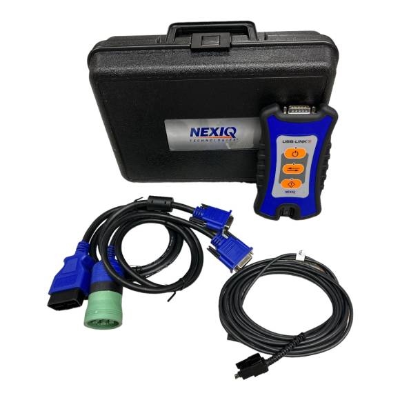
NEXIQ USB Link 3 Wired (NQ121054) Heavy-Duty Diagnostic Setup, Workflow, and Troubleshooting
Connect, communicate, flash, and troubleshoot like a senior diesel diagnostic technician.
.png_1779675736.png)
A field-tested procedural reference for technicians deploying the NEXIQ 121054 USB Link 3 Wired Edition across Class 6 through Class 8 diagnostic work.
Why a Reliable Wired Diagnostic Connection Is Non-Negotiable
Modern heavy-duty diagnostics are not a passive read of a fault code list. Today's technician routinely runs ECU flashes, parameter file uploads, forced DPF regenerations, injector trims, brake calibrations, transmission relearns, and live data streams across the J1939 backbone. Every one of these workflows assumes a stable, uninterrupted handshake between the diagnostic PC and the vehicle's gateway controller for the entire procedure.
A dropout in mid-flash can corrupt an ECU. A Bluetooth glitch during an injector calibration can leave the engine running rough until the procedure restarts from zero. A Wi-Fi channel collision during a TCM update can leave the truck undrivable. The NEXIQ 121054 USB Link 3 Wired Edition removes wireless instability from the equation entirely, giving the technician a hardwired path the software can rely on for the full session — measured in seconds for a fault read or in hours for a complete aftertreatment service procedure.
The NQ121054 Diagnostic Workflow Checklist
Follow this ordered procedure for every diagnostic session. Each step has a real reason behind it, and skipping one is where most shop diagnostic problems originate.
- Verify Software Installation and Driver Status Before Connecting the VCI. Open Device Manager on the diagnostic PC and confirm the NEXIQ USB-Link 3 driver is installed and reports no error state. The driver is bundled in the NEXIQ Device Drivers Application — install it from the NEXIQ website before plugging the VCI in for the first time. Confirm the OEM diagnostic software you intend to use (DDDL, INSITE, Davie4, PTT, etc.) is installed, licensed, and shows the USB-Link 3 as an available RP1210 adapter in its hardware setup menu. Tools needed: laptop running Windows 10 or 11, internet access for driver download, valid OEM software subscription. Common mistake: connecting the VCI before installing drivers, which causes Windows to register an "Unknown Device" entry that must later be cleared.
- Perform a Power Continuity Check on the Vehicle Diagnostic Port. Inspect the 9-pin or 16-pin diagnostic connector on the truck for damaged, bent, or corroded pins before inserting the cable. With ignition off, use a multimeter to verify pin 9 of the Deutsch 9-pin shows nominal 12V or 24V battery voltage, and that pins C and D (CAN H and CAN L) show approximately 60 ohms termination across the bus. Tools needed: multimeter, dental pick or pick set, contact cleaner if oxidation is visible. Torque specs: not applicable, but cable retention clip must seat fully. Common mistake: plugging into a port with one bent pin and forcing the connector — this damages both the cable and the truck-side connector, leading to intermittent communication failures later.
- Connect Hardware in the Correct Order: Vehicle → Adapter → VCI → USB → PC. This sequence matters. First seat the 9-pin or 16-pin diagnostic adapter into the truck. Second, connect the adapter to the USB Link 3 VCI body. Third, connect the latching USB cable to the VCI. Fourth, connect the USB cable to the laptop. This order prevents inrush current spikes through the laptop's USB controller and lets the VCI negotiate with the vehicle electrical system before the PC tries to enumerate it. Tools needed: included 9-pin Deutsch cable (493128) for J1939-equipped trucks; included 16-pin OBDII cable (493113) for J1962-equipped vehicles. Common mistake: connecting USB first, then plugging into the truck — this is the most common cause of "USB-Link not found" errors at session start.
- Verify Communication Inside the OEM Application Before Beginning Diagnostics. Open the OEM software, navigate to the connection or adapter test menu, and confirm the application sees the NEXIQ USB-Link 3 as the active RP1210 device. Initiate the connection test and read the ECU identification data first — VIN, software part number, calibration ID — before opening fault tables or programming functions. This single step confirms three things: the VCI is talking to the ECU, the ECU is responding with valid data, and the software has the correct vehicle profile loaded. Tools needed: licensed OEM software (DDDL 8.x or later for Detroit; INSITE 8.x or later for Cummins; Davie4 for PACCAR). Common mistake: jumping directly to a flash procedure without first reading ID data, which masks adapter or licensing problems until mid-procedure.
- Disconnect in Reverse Order and Confirm Session Closure. Close the OEM software session cleanly using the application's disconnect or close menu — never just yank the cable. Wait for the USB Link 3's status LED to indicate idle. Then unplug the USB cable from the laptop, then from the VCI, then disconnect the diagnostic adapter from the truck. This reverse-order disconnect protects the ECU from any open session state and prevents the USB controller from registering a hot-unplug fault. Tools needed: none beyond the active session. Common mistake: pulling the diagnostic adapter from the truck with the OEM software still open and the USB cable still connected — this can leave the ECU in a partially-initialized diagnostic mode that requires a key cycle to clear.
🛠 PRO-TIP: Always Export Baseline Parameters Before Any Flash
Before any flash programming session, log the truck's current ECU parameters using the OEM software's parameter export function. If the flash fails mid-process, you will have the original calibration values on hand to roll back instead of guessing at factory defaults. Save the parameter file with the VIN and the date in the filename — it costs ninety seconds and has saved many shops a full module replacement.
Troubleshooting Common Issues
Symptom 1: USB Link 3 Not Recognized by Windows
Open Device Manager and look under "NEXIQ Devices" or "Universal Serial Bus controllers" for the USB-Link 3 entry. If it appears with a yellow warning triangle, uninstall the device and reinstall the NEXIQ Device Drivers Application from the latest release. Try a different USB port — preferably a direct port on the laptop chassis rather than through a USB hub or docking station. Test the included latching USB cable for damage; replace it if the connector shells are loose or the cable shows signs of strain at the boots.
Symptom 2: VCI Connects but No Vehicle Communication
This is almost always a vehicle-side issue. Verify the diagnostic adapter is fully seated. Confirm vehicle ignition is in the correct position — most procedures require key-on, engine-off (KOEO). Check for a blown 7.5A diagnostic circuit fuse, often labeled "DIAG" or "DLC" in the cab fuse panel. On older trucks, verify J1708 termination is intact. If communication is intermittent, swap to a known-good diagnostic adapter to rule out a damaged cable.
Symptom 3: Session Drops During Flash Programming
On a wired VCI, this is virtually always a vehicle voltage problem rather than a communication issue. Install a battery support unit (BSU) before any flash and verify it holds 13.5V to 14.0V at the battery posts throughout the procedure. Verify shore power on shop chargers is solid. Never flash with the engine running unless the OEM specifically calls for it — alternator ripple introduces electrical noise that can interrupt sensitive programming sequences.
Symptom 4: ECU Visible in Software but Won't Read Faults
On modern trucks, gateway-protected modules require authentication before the ECU will release fault data. Confirm DoIP is enabled in the OEM software's protocol settings. Verify your subscription or license is active for that specific OEM platform. Some 2023 and newer trucks require an online security token request that fails silently if the laptop has no internet connection at the moment of authentication.
Symptom 5: Intermittent Communication Errors on a Wired Link
Rare on a wired VCI, but worth checking systematically. Inspect the cable strain at the VCI body — the latching USB connector should seat with a positive click. Examine the 9-pin or 16-pin diagnostic adapter for worn pins; replace if any pin shows visible wear or oxidation. Verify the USB cable is fully seated on both ends. If errors persist, swap to a known-good USB cable to rule out a fatigued conductor.
Tool Compatibility, Engines, and Equipment Platforms
The NQ121054 covers the broad span of heavy-duty diesel and commercial vehicle platforms currently in service, including:
- Detroit Diesel: DD13, DD15, DD16, Series 60, MBE4000, MBE900
- Cummins: ISX15, X15, ISX12, X12, ISB6.7, B6.7, L9, ISL, ISC8.3
- PACCAR: MX-13, MX-11, PX-9, PX-7
- Volvo / Mack: D11, D13, D16, MP7, MP8, MP10
- International / Navistar: A26, N13, MaxxForce 13, DT466
- Allison Transmissions: 1000, 2000, 3000, 4000 series
- Eaton Transmissions: Fuller, UltraShift, Procision
- Bendix / Wabco / Haldex: Brake systems with EBS and ESP modules
- Caterpillar: Older on-highway and select off-highway platforms via appropriate adapter
The same VCI also supports yellow-iron equipment, refuse trucks, transit buses, and stationary diesel generators wherever the controller speaks J1939, J1708, or CAN FD. With the correct OEM-specific cable, the NQ121054 functions as a single-interface solution across nearly the entire commercial diesel landscape.
Safety & Shop Best Practices
- Always install a battery support unit before flash programming. ECU flashes pull steady current and any voltage drop below 12.4V mid-flash can brick the module.
- Never disconnect a VCI mid-session. Always close the diagnostic application first and wait for the VCI's status LED to indicate idle.
- Avoid running diagnostics with the engine running unless the OEM procedure requires it. Alternator ripple introduces electrical noise into the diagnostic line.
- Use a USB extension only when necessary, and only with shielded industrial-grade cables. Cheap USB extensions degrade signal integrity and introduce intermittent dropouts that mimic adapter failures.
- Treat the VCI like a calibrated instrument. Drops onto concrete floors can damage internal protocol controllers even if the case appears undamaged.
- Keep firmware updated. NEXIQ releases periodic firmware updates that improve protocol handling and OEM compatibility.
- Store the VCI in its plastic carrying case when not in use. The case protects the connectors and keeps cables organized between jobs.
Technician-Focused FAQ
Q: Should I update USB Link 3 firmware before first use?
A: Yes. Install the latest NEXIQ Device Drivers Application from NEXIQ's site, then run the firmware update utility before connecting to a vehicle. This ensures the VCI ships with current protocol handling for newer truck architectures.
Q: Can I use the NQ121054 with multiple OEM software platforms on the same laptop?
A: Yes. RP1210 architecture allows multiple OEM applications to share a single VCI driver. You do not need to reinstall the driver for each platform — DDDL, INSITE, Davie4, and PTT can all coexist on the same machine.
Q: Will the USB Link 3 work through a USB-to-Ethernet adapter for long cable runs?
A: Not directly. The VCI is designed for direct USB connection. For runs longer than the included 15-foot cable, use a powered USB extender designed for industrial applications — passive extensions over a few extra feet usually fail.
Q: Why does my software show "Adapter Not Found" even though the VCI is plugged in?
A: Most often this is a driver selection issue inside the OEM software's adapter setup menu. Confirm "NEXIQ USB-Link 3" is selected as the active RP1210 device — not the Link 2, not a different brand, and not a previously installed adapter that left a phantom registry entry.
Q: Does the NQ121054 support J1939 Network Bridge functions for multi-bus trucks?
A: It supports the standard J1939 protocol stack including FD variants. Multi-bus bridging is typically handled by the truck's gateway ECU rather than the VCI itself.
Q: What is the practical difference between the wired NQ121054 and the wireless USB Link 3?
A: Hardware-identical protocol support, but the wired edition removes Bluetooth and Wi-Fi entirely for maximum signal reliability. Choose wired for fleet shops, body shops, and any environment with RF interference; choose wireless only when the laptop must stay distant from the truck and signal conditions are known to be clean.
Q: Can a field technician power a laptop and VCI from the truck cab?
A: Yes. Many field techs use a 12V inverter and short USB cable run for cab-based diagnostics. The NQ121054 draws power from the diagnostic port and the laptop's USB bus, so no additional power source is required for the VCI itself.
Q: Is the included quick start guide enough to get going, or do I need formal training?
A: A technician already familiar with RP1210 diagnostics can be productive with the included quick start guide within an hour. Operators new to heavy-duty diagnostics should pair the VCI with OEM-specific software training.
Equip Your Bay With a Diagnostic Interface That Doesn't Drop the Connection
The NEXIQ 121054 USB Link 3 Wired Edition (NQ121054) is in stock at Apex Tool Company. $740 — free shipping on orders over $500 within the continental US.
ORDER NQ121054 →Call 812-579-5478 or 800-365-2233 — Mon–Fri 8 a.m.–5 p.m. ET
overall rating:
my rating:
log in to rate