
Blog
Universal Liner Puller Foot Replacement & Maintenance Steps
Precision tool maintenance guidelines for heavy diesel rebuilders and fleet mechanics.
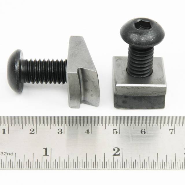
Servicing heavy-duty diesel engine blocks and preparing your universal liner puller for a major overhaul job? Follow this step-by-step professional workshop procedure to inspect worn puller fingers, install the M50010-20 thick replacement feet set, align retaining screws, and safely extract cylinder sleeves without risking block bore damage.
Why Worn Puller Feet Cause Catastrophic Engine Block Bore Scoring
On commercial diesel engines, cylinder liners are held firmly by tight press fits, carbon deposits, and dried o-ring seals. Pulling these liners requires pulling force transferred entirely through the lower feet of the universal liner puller tool. Over repeated uses, the sharp landing edges of thin puller feet gradually wear down, round off, or bow outward. Technicians who continue using worn puller feet face severe mechanical risks. As the forcing screw is tightened under high torque, worn feet lose grip on the narrow liner flange and slip off. The sudden, high-pressure release causes the puller assembly to kick sideways, driving the hardened steel foot edge deep into the polished engine block bore wall. A gouged engine block wall destroys bore concentricity and prevents fresh cylinder liner o-rings from sealing, turning a routine overhaul into an expensive block machining nightmare or forcing a complete engine block scrap. Installing the M50010-20 Thick Replacement Feet Set completely eliminates these extraction risks. Featuring a thicker profile and fresh, sharp landing shoulders, these feet grip maximum flange surface area, providing 100% positive mechanical engagement to pull liners smoothly and safely.
The 5-Step Universal Liner Puller Foot Replacement Protocol
- Inspect Existing Puller Feet & Retaining Screws: Clean the lower pivot block of your Apex or Kent-Moore Universal Liner Puller tool. Inspect existing feet for rounded contact lips, cracks, or bowed geometry.
- Unbolt & Remove Worn Puller Fingers: Using the appropriate hex key or screwdriver, unbolt the retaining screws holding the old feet to the spring-loaded pivot block. Remove old feet and discard worn hardware.
- Clean Pivot Block Recess & Apply Thread Locker: Clean the pivot block mounting slots and threaded holes using solvent and a wire brush to remove grit and old thread sealant. Apply medium-strength thread locker to the fresh screws included in the M50010-20 kit.
- Install M50010-20 Thick Feet & Torque Screws: Position the fresh M50010-20 thick feet into the pivot block slots. Thread in the new retaining screws and torque firmly. *Verify that both feet pivot smoothly and spring outward freely without binding.*
- Test-Fit Tool & Execute Smooth Liner Extraction: Lower the liner puller assembly into the target cylinder sleeve until the feet spring outward and catch firmly under the bottom liner flange. Turn the main forcing screw clockwise using manual tools to pull the sleeve straight out with zero slippage.
PRO-TECH THREAD LOCKER & PIVOT SPRING CHECK MANDATE:
ALWAYS APPLY THREAD LOCKER to foot retaining screws! Loose foot screws can back out inside an engine block during extraction! ALWAYS verify that the internal spring extends both feet evenly so they engage the liner flange 100% symmetrically!
1.00 lb High-Strength Alloy Tool Steel Replacement Feet Set. Protect Engine Blocks.
Get the M50010-20 Feet Set Now
overall rating:
my rating:
log in to rate