
Blog
Cummins Engine Counterbore Machining Steps
Precision engine block machining and deck restoration guidelines for commercial diesel mechanics and machine shops.
Resurfacing upper cylinder liner counterbores on a Cummins ISX, L10, M11, or C Series engine block? Follow this step-by-step professional workshop procedure to inspect cutter plates, install the PT-2210-12 carbide cutting bit, set depth adjusters using traction grooves, execute smooth cutting passes, and verify counterbore seat flatness.
Why Worn Cutting Bits Cause Uneven Liner Height & Blown Gaskets
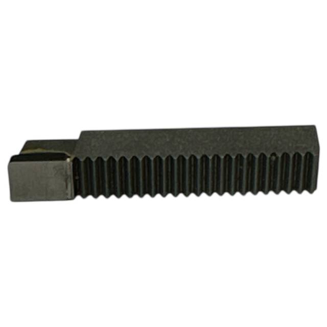
On heavy-duty Cummins engines, the cylinder liner protrusion must be consistent across all cylinders to guarantee equal head gasket fire ring crush. When a counterbore ledge develops fretting wear, machining a smooth, clean ledge is the only way to restore proper liner height using counterbore shims. However, technicians who attempt counterboring using dull or chipped cutting bits create severe engine block damage. A dull bit pushes metal rather than cutting it, generating excessive heat that warps the cast-iron ledge and creates deep chatter ridges. When a stainless steel shim is placed over a chattered ledge, the shim deforms under head bolt torque, causing the cylinder liner to drop during engine operation. A dropped liner loses clamping pressure, blowing the head gasket and leaking coolant into the oil pan. Utilizing a fresh PT-2210-12 Carbide Cutting Bit eliminates machining defects completely. The bit's sharp carbide edge slices smoothly through cast iron, producing a mirror-smooth, dead-flat seat that supports counterbore shims evenly across 360 degrees.
The 5-Step Cummins Counterbore Machining & Bit Setup Protocol
- Inspect Tooling & Clean Cutter Plate: Clean the counterboring tool assembly thoroughly. Inspect the bit holder slot on the cutter plate to ensure it is free of metal shavings, rust, or debris.
- Install PT-2210-12 Bit into Cutter Plate: Slide the PT-2210-12 bit into the cutter plate holder, ensuring the shank's traction grooves align cleanly with the bit adjuster screw mechanism.
- Set Counterbore Cutting Diameter & Depth: Adjust the bit holder to set the correct cutting diameter for the specific Cummins engine series (ISX, L10, M11, or C Series). Lock the bit adjustment set screw firmly to secure the bit in position.
- Mount Tool on Block & Execute Smooth Cutting Passes: Anchor the counterboring tool securely to the engine block deck. Turn the tool drive handle smoothly while applying light, uniform downward feed pressure to cut the counterbore ledge cleanly.
- Vacuum Shavings & Inspect Machined Ledge: Stop cutting once the target depth is reached. Vacuum out iron chips, clean the counterbore ledge with solvent, and inspect the surface with a depth gauge to ensure a dead-flat, chatter-free finish before installing shims.
PRO-TECH BIT INSPECTION & FEED PRESSURE MANDATE:
ALWAYS INSPECT THE CARBIDE EDGE BEFORE CUTTING! Never use a chipped or dull bit, as damaged edges WILL cause chatter marks and uneven ledges! ALWAYS APPLY CONSTANT, LIGHT FEED PRESSURE—never force or slam the cutter tool onto the cast iron ledge!
Micro-Grain Carbide Precision Counterbore Bit. Protect Engine Overhauls.
Get the PT-2210-12 Bit Now
overall rating:
my rating:
log in to rate