
Blog
Tracing Diesel Air Leaks with the M50042 Sight Glass
Precision low-pressure fluid loop reconditioning guidelines for fleet service stations.

Dealing with an unexplainable rough idle or a low-pressure hesitation code on a Caterpillar, Cummins, or Detroit block? Learn the professional technical sequence to inline-plumb the M50042 #8 indicator and catch hidden bubbles.
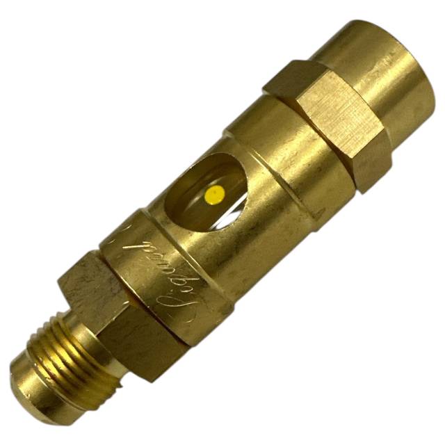
Why Clear Visual Tracking Stops Parts-Cannon Diagnostic Waste
When a heavy-duty commercial rig develops an air ingress leak along its fuel suction circuit, it often mimics a failing primary transfer pump or a set of weak common-rail injectors. If a shop supervisor lacks a definitive way to audit fluid clarity before it hits the high-pressure loop, they fall straight into the trap of parts-cannon diagnostics—replacing high-value components on a loose guess. Utilizing a dedicated in-line viewing window like the M50042 lets you pinpoint the issue with precision. If you see white foam or a continuous stream of micro-bubbles rushing past the window, you have verified an air leak. By systematically moving the sight glass upstream, you can isolate the exact leaking connection, keeping your service lane highly efficient and avoiding unnecessary, high-cost component swaps.
The 5-Step Low-Pressure Loop Isolation Protocol
- 场地De-Pressurize and Clean Target Ports: Turn the vehicle ignition off and allow fuel system temperatures to settle. Locate the target low-pressure fluid loop segment (such as the line leading from the fuel filter block to the transfer pump inlet). Thoroughly clean all surrounding grease and grit from the connections.
- Thread the M50042 Inline Assembly: Back out the factory hose fittings carefully, managing any residual fluid drops with a clean shop towel. Insert the M50042 sight glass inline into the loop. Thread the 3/4-16 45-degree flared joints down evenly by hand to ensure the seating faces do not cross-thread or cock off-axis.
- Torque the Joints to a Vacuum-Tight Seal: Secure the sight glass collar with a backup wrench and use your hand tools to snug the fittings to exact manual specifications. *Note: Threading a flare fitting demands a perfectly centered, flat alignment to guarantee an absolute, airtight mechanical seal that won't draw extra air into the test loop.*
- Prime and Purge the Tracking Field: Operate the vehicle's manual hand priming pump plunger or cycle the electrical fuel pump to bleed air pockets introduced during the tool installation. Cycle until the clear glass port window fills completely with solid, steady diesel fuel.
- Monitor the Fluid Stream Under Engine Load: Start the engine and run it at a steady idle speed. Look directly through the clear glass port, utilizing the identification dot to help orient your focus against moving fluids. A perfectly sealed loop will show a completely solid, transparent stream. If a consistent column of bubbles or foam appears, an air leak is active upstream of the tool. Relocate the window further up the circuit to pinpoint the exact leak track.
PRO-TECH FLUID PRESSURE REGULATION DIRECTIVE:
The M50042 inspection sight glass is custom-engineered and certified exclusively for **low-pressure diagnostic fluid streams (such as suction loops, return lines, or gravity-fed lines)**! Never install this glass assembly inside a high-pressure common-rail fuel track or high-pressure hydraulic lines. Extreme multi-thousand PSI surges will instantly shatter the glass lens, causing an immediate fluid blowout, fire hazard, or severe workshop injury risk. Always verify your loop operating limits before completing the connection.
3/4-16 Flare Mechanical Integration. Stop Guessing Upstream Leak Tracks.
Get the #8 In-Line Sight Glass Now
overall rating:
my rating:
log in to rate