
Blog
Re-Calibration of Cummins STC Tappet Assemblies
Precision overhead structural powertrain reconditioning guidelines for logistics fleets.

Performing a top-end tune-up or reassembling an overhead rocker assembly after a major engine rebuild? Learn the precise technical sequence to map clearances using the M20129 tool.
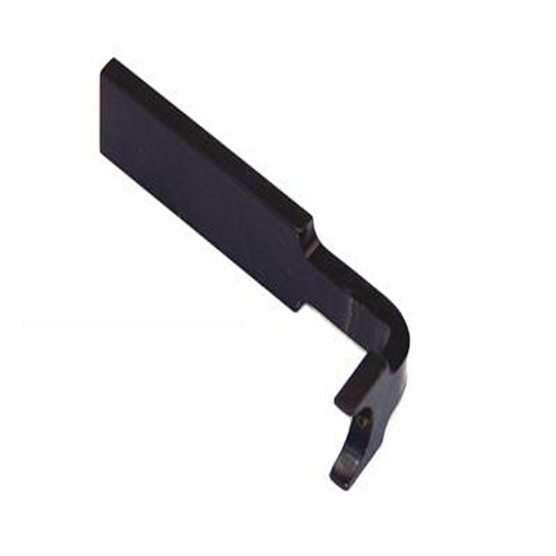
Why Loose Tool Clearance Slips Cause Severe Valvetrain Mounding Wear
The mechanical clearances on a Cummins STC engine block manage critical force transfer paths. When a technician tries to adjust the valve levers or fuel injector preload settings using loose universal sockets or offset open wrenches, the tool frequently slants or binds across the hex flat. This lack of positive engagement introduces un-tracked variations into the feeler gauge thickness check. If a valve lash is set too loose, the pushrod bridge experiences hard mechanical hammering shocks at high RPM, cracking the crossheads. If it is set too tight, the valves fail to seat completely flat against the cylinder deck face—allowing combustion fire to leak past the seat and scorch the valve guides. Utilizing a dedicated application tool like the M20129 ensures that your leverage stays perfectly straight, protecting the fine adjustment threads and ensuring a tight, repeatable calibration across all six cylinder wells.
The 5-Step Overhead Valve & Injector Setting Protocol
- 场地Rocker Housing Cleanout and Triage: Pull the valve valve cover assemblies. Clean away caked oil crust and fluid scale from the rocker shaft housing banks using clean shop towels, establishing a spotless mapping area.
- Locate Top Dead Center (TDC) Indexing: Bar the engine over manually using a crankshaft rotation tool until the internal timing marks on the gear housing align with the cylinder #1 TDC compression stroke limit.
- Seat the M20129 Adjusting Wrench: Position the precision-cut head of the M20129 tappet tool directly onto the targeted valve or injector locknut screw assembly. Slide the tool home fully, verifying a flush, zero-wobble engagement over the hex head.
- Map the Precision Feeler Clearance: Slide your matching specification feeler gauge blade under the rocker lever landing pad. Turn the center adjustment knob smoothly with your M20129 tool handle until you feel a firm, parallel drag on the metal strip. Lock the outer jam-nut firmly while using the tool to hold the center adjustment thread dead-centered and stationary.
- Bar and Cycle through the Timing Pattern: Remove the tool cleanly. Bar the crankshaft over to progress down the factory cylinder sequence. Repeat your valve lash and injector loading checks on each remaining position until the complete overhead tune-up satisfies factory service parameters.
PRO-TECH STC PRELOAD RE-CHECK DIRECTIVE:
Always double-check your injector locknut torque values after running the final tightening pass! Because Step Timing Control fuel links operate through high-pressure oil ports, a loose jam-nut allows the adjustment thread to drift loose under load—causing immediate power loss and extreme exhaust smoking. Never use pneumatic air impact tools to run the adjustment screws down.
Class 8 Top-End Accuracy. Protect Fine Adjuster Screw Threads.
Get the Cummins 3823348 Alternate Tool Now
overall rating:
my rating:
log in to rate