
Blog
Universal Liner Height & Counterbore Depth Measurement Steps
Precision deck metrology guidelines for commercial fleet and heavy diesel mechanics.

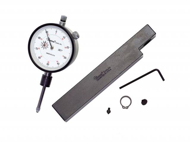
Preparing a heavy-duty diesel cylinder block deck for cylinder head installation? Follow this step-by-step professional workshop procedure to clean deck lands, select correct tip anvils, zero the ATC6434 sled gauge, and take 4-point circumferential readings to verify counterbore depth and liner protrusion.
Why Deck Geometry Metrology Prevents Repeat Engine Overhaul Failures
Heavy-duty commercial diesel engines operate under extreme thermal expansion and high peak combustion pressures. Maintaining structural sealing between the cylinder head, head gasket, and cylinder block deck requires exact mechanical alignment. During engine reconditioning, verifying both counterbore depth (before liner insertion) and liner protrusion (after liner clamping) is non-negotiable. If a machinist cuts counterbores without measuring depth across all 360 degrees, the counterbore ledge will be uneven, causing the new liner flange to sit canted. Furthermore, if a mechanic fails to clamp cylinder liners to full specification before taking protrusion measurements, un-clamped liners yield false high readings. Once the cylinder head is torqued, the liners settle lower than expected, destroying gasket crush and allowing combustion fire rings to blow. Utilizing a universal deck reference sled like the ATC6434 allows mechanics to zero the indicator directly on the clean block deck and take precise readings anywhere on the block. Switching between pointed contact tips (for narrow liner lip protrusion) and flat contact tips (for wide counterbore ledges) ensures total metrology accuracy across any diesel engine platform.
The 5-Step Universal Deck Metrology Protocol
- Block Deck & Counterbore Surface Prep: Scrub the top deck face of the cylinder block, liner top flange rim, and counterbore ledges thoroughly using solvent and stone blocks. *CRITICAL: Ensure zero carbon, rust, scale, or oil burrs remain on measuring surfaces.*
- Select Contact Tip & Zero ATC6434 Gauge: Thread the pointed tip (for liner protrusion) or flat tip (for counterbore depth) into the dial indicator stem. Rest the precision-ground steel sled feet flat on a clean section of the block deck adjacent to the cylinder bore. Rotate the outer bezel dial to set the needle to absolute ZERO.
- Measure Counterbore Ledge Depth (Pre-Assembly): Lower the indicator tip onto the counterbore ledge land. Record depth readings at four points 90 degrees apart (12 o'clock, 3 o'clock, 6 o'clock, 9 o'clock) to verify counterbore machining flatness and determine required shim thickness.
- Clamp Liners to Full OEM Specification: Insert cylinder liners into block bores (without lower seals for initial mock-up). Install hold-down clamping plates/bolts and torque them to specified engine service manual torque to fully seat the liner flange into the counterbore ledge.
- Take 4-Point Protrusion Readings & Evaluate: Zero the ATC6434 sled gauge back on the block deck. Slide the sled until the pointed tip rests on the top rim of the clamped liner flange. Record readings at four circumferential points around each cylinder. Verify that total variation around a single liner and between adjacent cylinders falls strictly within OEM factory limits before final head installation.
PRO-TECH TIP SELECTION & CLAMPING MANDATE:
Always use the pointed contact tip for narrow liner rims to prevent tip bridging errors, and always torque liner hold-down bolts to full spec before measuring protrusion! Taking readings on un-clamped liners gives false high values, leading to incorrect shim selection and blown head gaskets!
Universal Steel Sled Metrology. Protect Commercial Engine Overhauls.
Get the ATC6434 Universal Dial Depth Gauge Now
overall rating:
my rating:
log in to rate