
Blog
CAT 3406E & C15 Counterbore Machining Steps
Precision deck machining guidelines for commercial fleet and Class 8 mechanics.
Repairing fretted or eroded liner ledges during an in-frame overhaul on a Caterpillar 3406E, C15, or 3306 engine? Follow this step-by-step professional workshop procedure to clean block deck landings, anchor the M52051 three-legged base, set micrometer cutting depth, and machine perfectly flat counterbores to match shim specifications.
Why Fretted Counterbores Destroy CAT Cylinder Head Gaskets
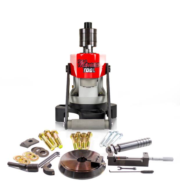
On Caterpillar heavy-duty diesel engines, wet cylinder liners rest directly on a machined cast-iron counterbore ledge at the top of the block deck. Because combustion fire-ring seals rely on uniform compression from cylinder head bolts, liner protrusion above the deck must remain strictly within factory limits (typically 0.003″ to 0.006″ / 0.08 mm to 0.15 mm). When engine miles accumulate, micro-friction and coolant erosion eat away at the counterbore ledge. If a technician installs new liners over a fretted or uneven counterbore without remachining the ledge, the liner sits crooked or drops low under head bolt torque. This results in immediate head gasket fire-ring failure, pressurizing the radiator and washing out engine bearings with coolant. Utilizing the Made In USA 91-pound M52051 counterbore boring tool allows mechanics to resurface damaged ledges directly in the vehicle chassis. By anchoring its rigid three-legged frame to the head bolt holes and adjusting the micro-feed spindle, the tool cuts a glass-smooth, perfectly flat landing. Adding precision CAT counterbore shims restores exact factory liner protrusion, guaranteeing a 100% leak-free, high-compression overhaul.
The 5-Step CAT Counterbore Machining Protocol
- Block Deck Surface Prep & Inspection: Clean the cylinder block deck and target counterbore ledge thoroughly using solvent, stone blocks, and shop vacuum. Inspect the ledge for cracks or severe erosion to determine required machining depth.
- Anchor M52051 Base & Mount Cutter Head: Position the M52051 three-legged base squarely over the target cylinder bore. Thread mounting hold-down studs into adjacent head bolt holes and torque securely to ensure 100% rigid, vibration-free clamping. Install the correct size cutter head insert (sold separately).
- Set Zero Depth & Micrometer Feed: Lower the boring spindle until the carbide cutting insert contacts the clean counterbore ledge. Zero the precision micrometer depth gauge and set desired cut depth (typically 0.001″ to 0.003″ per pass to clean up fretting).
- Machine Ledge with Removable Handle: Attach the removable handle assembly (utilizing its cab-clearance feature if working under tight engine cowls). Turn the drive spindle smoothly by hand while advancing the micro-feed. Maintain steady rotation until the cutter completes a full 360-degree flat pass.
- Clean, Measure & Install Shims: Vacuum away all cast-iron chips and wipe the counterbore ledge clean. Use a metric/inch dial depth indicator (such as the ATC 1P-2402) to measure final depth. Install corresponding Caterpillar counterbore shims, seat the cylinder liner, and verify 4-point protrusion before head installation.
PRO-TECH RIGID CLAMPING & CLEANUP MANDATE:
Always torque the M52051 base hold-down studs securely into clean deck threads before machining! Loose mounting legs cause cutter chatter, resulting in a rough counterbore surface. Thoroughly vacuum all metal cuttings out of cylinder bores and oil passages prior to installing liner shims!
Made In USA 91 lb Professional Machining Tool. Protect Caterpillar Engine Overhauls.
Get the M52051 Counterbore Boring Tool Now
overall rating:
my rating:
log in to rate