
Blog
CAT C-15 & Cummins ISX Piston Installation Steps
Precision engine assembly guidelines for commercial fleet and Class 8 mechanics.
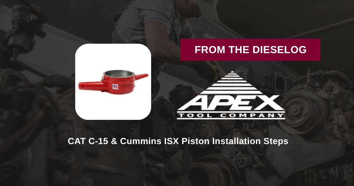
Installing piston assemblies into a Caterpillar 3406E/C-15 or Cummins ISX15 engine block? Follow this step-by-step professional workshop sequence to stagger ring end gaps, apply assembly lube, latch the ATC-7040 clamshell compressor, and guide pistons safely into 5.400″ cylinder liners.
Why Improper Ring Compression Causes Oil Consumption & Low Compression
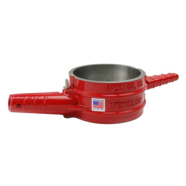
Heavy-duty 15-liter diesel engines rely on precise ring-to-liner wall sealing to hold combustion pressures above 2,000 PSI while scraping oil cleanly off liner walls. During engine assembly, inserting a piston fitted with fresh ring lands into a cylinder liner requires collapsing the rings down to exact cylinder diameter. If a mechanic attempts to force a piston into the bore using flexible band tools or makeshift drivers, uneven pressure allows ring ends to flare outward. As the piston moves down into the block deck, the sharp liner entrance chamfer clips the expanded ring edge. This results in broken ring lands, bent oil ring expander springs, or severe vertical gouges along the cross-hatched liner wall. Upon initial engine startup, the damaged cylinder experiences immediate blow-by, low compression, and high oil consumption. Utilizing a rigid 5.400″ clamshell tool like the 9-pound ATC-7040 encapsulates the entire ring pack in a precision-machined steel sleeve. The tool rests flat against the block deck, allowing the piston to be tapped smoothly down a dead-straight axis without catching or damaging ring edges.
The 5-Step Heavy-Duty Piston Installation Protocol
- Liner Bore Prep & Ring Staggering: Clean the cylinder liner bore bone-dry and coat with clean engine assembly oil. Install ring packs onto the piston, ensuring correct ring orientation (marking facing UP). Stagger ring end gaps at 120-degree intervals per OEM service manual guidelines (never align ring gaps with wrist pin bores).
- Apply Assembly Lubricant & Position Rod: Generously lubricate the piston skirts, ring lands, and rod journal bearings with heavy engine assembly lube. Rotate the crankshaft so the target rod journal rests at Bottom Dead Center (BDC). Align the connecting rod orientation notch facing the front of the engine.
- Latch ATC-7040 Clamshell Compressor: Open the ATC-7040 5.4″ ring compressor clamshell and place it around the piston assembly over the ring pack. Latch the locking mechanism securely. Verify that all ring lands are contained 100% inside the tapered internal sleeve.
- Align Compressor Flat Against Block Deck: Lower the connecting rod down into the cylinder liner until the base of the ATC-7040 compressor rests completely flat against the top deck of the block/liner face. Hold the compressor body down firmly to eliminate any gap between the tool base and liner entrance.
- Tap Piston Smoothly into Liner: Using a wooden or plastic hammer handle, apply light, centered taps to the crown of the piston. The piston will slide smoothly out of the ATC-7040 sleeve down into the 5.400″ liner bore. *CRITICAL: If high resistance is felt, STOP immediately! Remove the compressor and inspect ring lands for catch points before re-tapping.* Unlatch and remove the ATC-7040 tool, then torque rod cap bolts to factory spec.
PRO-TECH DECK-SEATING MANDATE:
Always maintain firm downward hand pressure on the ATC-7040 compressor body while tapping the piston crown! If the compressor lifts off the deck face during tapping, ring lands will expand into the gap and snap against the liner edge instantly!
Made In USA Heavy-Duty Steel Clamshell. Protect CAT & Cummins Piston Overhauls.
Get the ATC-7040 Ring Compressor Now
overall rating:
my rating:
log in to rate