
Blog
Class 8 Dual-Disc Clutch Alignment Steps
Precision lower-block structural drivetrain reconditioning guidelines for freight fleets.
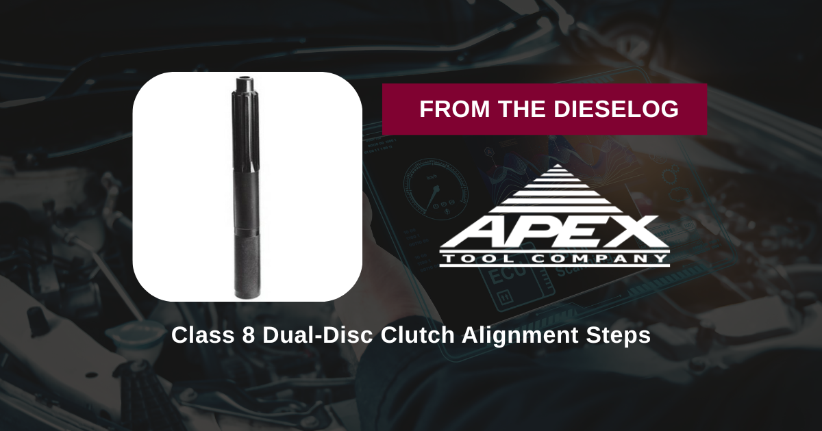
Dropping a fresh clutch pack into a heavy Mack, Freightliner, or Peterbilt rig? Learn the proper technical sequence to index dual splines and secure pressure plates safely using the OTC-7072A composite tool.

Why Tool Sag and Extension Forcing Destroys Premium Hub Castings
The massive pressure plates on heavy commercial vehicles apply thousands of pounds of clamping load to secure friction elements. When a line mechanic tightens down the pressure plate mounting pattern using a flimsy, low-grade plastic dummy shaft, the weight of the massive dual discs causes the tool to sag downward. This minor deflection pulls the rear friction disc off-center relative to the forward disc hub. When you try to hoist the transmission into position, the input shaft will easily slide through the first disc, but slam hard against the crooked splines of the second. Forcing the gearbox home using mounting bolts to draw the case flat will warp the metal disc plate or crush the dampener springs—guaranteeing a clutch that chatters, drags, or fails to release cleanly. Utilizing a rigid fiberglass-reinforced nylon shaft like the OTC-7072A keeps the entire spline column completely straight under maximum pressure, allowing for an effortless, drop-in stab.
The 5-Step Drivetrain Alignment Sequence
- Flywheel Housing and Pilot Bearing Triage: Inspect the flywheel surface face for thermal cracks or heat spots. Clean the splines and the internal bore of the new pilot bearing aggressively with solvent, ensuring the cavity is free of old grease dust or rust scale.
- Assemble and Stack the Friction Elements: Identify the "Flywheel Side" markings stamped onto your new clutch discs. Slide both friction elements onto the OTC-7072A alignment tool shaft in their correct operating sequence, making sure the tool's 1-1/2" O.D. teeth engage the inner splines fully.
- Seat the Tool Mandrel into the Pilot Bearing: Lift the loaded OTC tool mandrel assembly and guide the 1" pilot snout straight into the center flywheel bearing well. Push firmly until the tool seats flat and square against the crankshaft axis, mechanically centering both discs over the bearing line.
- Mount the Pressure Plate and Star Torque: Lift the heavy iron pressure plate housing cover over your alignment tool and hand-thread all the mounting bolts to the flywheel rim. Grab your torque wrench and tighten the fasteners down slowly in a progressive star pattern to factory specifications, squashing the heavy internal springs completely flat.
- Extract the Tool and Stab the Transmission: Once the pressure plate bolts are locked to spec, grab the comfortable handle of the OTC-7072A tool and pull it straight out along its axis. Because the fiberglass-nylon structure resists sticking, the tool will glide out cleanly without shifting the synchronized discs. Immediately slide your transmission jack forward to stab the input shaft home effortlessly.
PRO-TECH TRANSMISSION BOLT DRAW-DOWN WARNING:
Never use the bell-housing mounting bolts to force a transmission case flat against the engine block if it hangs up during a stab! If the transmission stops short by an inch, your splines are out of alignment. Forcing the case down with an impact gun will bend the clutch disc hubs, distort the clutch spring leaves, or crack the aluminum bell-housing ears. Pull the jack back, insert your OTC-7072A shaft to reset the disc centers, and slide it back in smoothly.
1-1/2″ Spline Synchronization. Eliminate Hub Distortion Hazards.
Get Your OTC-7072A Clutch Tool Now
overall rating:
my rating:
log in to rate