
Blog
Tech Guide: Cummins 855/NT/NH Splined Coupler Extraction Steps
Precision driveline maintenance guidelines for commercial fleet and Class 8 mechanics.
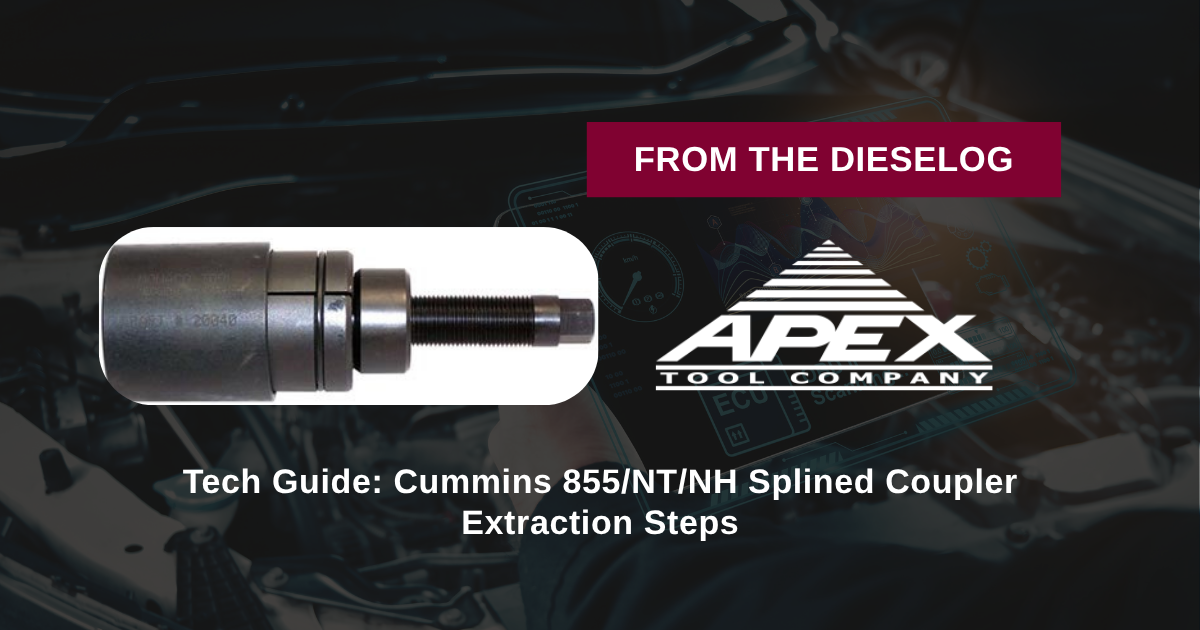
Removing press-fit air compressor or accessory drive splined couplers during engine teardown on a Cummins 855, NT, or NH engine? Follow this step-by-step professional workshop procedure to set up the M20040 collet puller, engage the coupler body, turn the forcing screw smoothly, and extract the hub without spline distortion.
Why Generic Gear Pullers & Torches Destroy Cummins Drive Assemblies
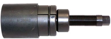
Press-fit splined couplers on Cummins NT, NH, and 855 engines operate under high torsional loading and feature tight interference tolerances. Because these couplers do not have threaded puller holes, mechanics often attempt removal using standard jaw pullers or pry bars. This is a severe service mistake. Standard two-jaw pullers apply point-loads to the outer edge of the unthreaded coupler, bending the shell out-of-round and gouging drive shaft splines. Worse, using torch heat to expand seized hubs alters the heat-treat metallurgy of the drive shaft and melts internal front gear case oil seals. When the engine is reassembled with a distorted coupler, the uneven spline engagement creates heavy vibration, rapidly destroying the air compressor drive gears and causing catastrophic oil leaks. Utilizing the dedicated 3-pound M20040 puller eliminates these repair hazards. Featuring a precision collet ring that clamps evenly around the coupler, the tool aligns its central forcing screw dead-center with the drive shaft. As the forcing screw advances, it draws the coupler straight off the shaft splines without side-cocking, preserving the shaft, splines, and surrounding housing seals for flawless reassembly.
The 5-Step Splined Coupler Extraction Protocol
- Clean & Inspect Drive Assembly: Disconnect air compressor mounting hardware to clear access to the drive coupling. Wipe away grease, rust, and road grime from the splined hub and shaft nose.
- Fit M20040 Collet/Jaw Housing: Position the collet/jaw assembly of the M20040 puller around the perimeter of the splined coupler. Ensure the inner gripping lip seats securely into the recessed locking groove of the coupler body.
- Align Central Forcing Screw: Thread the central forcing screw into the puller bridge until the drive point seats flat against the center dimple of the accessory drive shaft. Verify the tool is standing 100% perpendicular to the shaft face.
- Apply Smooth Mechanical Tension: Lube the forcing screw threads with heavy oil. Hold the puller body steady with a wrench while turning the central forcing screw clockwise using a manual socket or box wrench.
- Extract Coupler & Inspect Splines: Continue turning the forcing screw until the interference fit breaks and the splined coupler slides completely off the shaft. Remove the tool, inspect shaft splines and seal surfaces for wear, and clean for reassembly.
PRO-TECH MANUAL WRENCH & SHAFT CENTER MANDATE:
Always turn the forcing screw of the M20040 puller using manual hand wrenches! Never use high-speed pneumatic impact guns, which can shock-load and damage delicate shaft ends! Always ensure the forcing screw tip is centered directly in the shaft center dimple before applying heavy torque!
3 lbs High-Tensile Alloy Steel Tool. Protect Cummins Accessory Drive Overhauls.
Get the M20040 Coupler Puller Now
overall rating:
my rating:
log in to rate