
Blog
Cummins ISB, ISC & ISL Camshaft Gear Extraction Steps
Precision timing train reconditioning guidelines for commercial fleet and equipment mechanics.
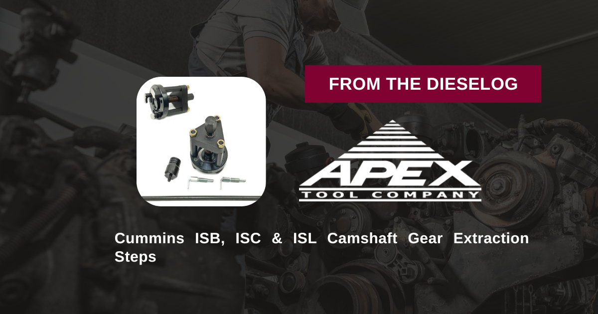
Replacing a front gear housing, servicing timing gears, or repairing front gear train components on a Cummins ISB 6.7, ISC 8.3, or ISL 9L engine? Follow this step-by-step professional workshop procedure to verify camshaft nose threading, mount the M20164-A remover tool, and pull pressed camshaft gears smoothly in-frame.
Why Improvised Gear Pullers Cause Severe Engine Damage
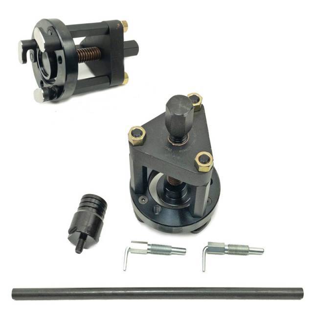
The camshaft gear on Cummins mid-range diesel engines drives both the valve timing train and fuel injection system under high mechanical loads. Because the gear uses a heavy interference press fit onto the camshaft nose, pulling it requires significant axial breakout force. A frequent mistake in repair shops is using universal 3-jaw pullers hooked onto the outer rim of the gear. As torque is applied to the forcing screw, the jaws place immense bending stress on the helical gear teeth, micro-fracturing or chipping the precision tooth profiles. Even worse, prying behind the gear with heel bars bends the camshaft thrust plate, causing end-play binding or destroying the camshaft journal when the engine is restarted. Utilizing a purpose-built removal kit like the 11-pound M20164-A anchors extraction forces directly into the internal threads of the camshaft nose via a pilot adapter. This creates a closed-loop mechanical system that pulls the gear straight off the shaft with zero load on timing teeth, thrust plates, or internal engine bearings.
The 5-Step Camshaft Gear Extraction Protocol
- Pre-Inspection & Thread Verification: Remove the front gear cover to access the camshaft gear. *CRITICAL CHECK: Inspect the center of the camshaft nose to confirm it features an internal threaded hole. The M20164-A kit requires this threaded opening to mount the pilot adapter.* Clean rust and oil out of the threads using solvent and shop air.
- Thread Pilot Adapter & Mount Remover Body: Thread the M20164-A pilot adapter shaft firmly into the threaded hole in the center of the camshaft nose until fully seated. Slide the main remover body over the pilot shaft and align its extraction legs with the designated mounting points on the camshaft gear hub.
- Secure Extraction Fasteners: Insert the heavy-duty kit extraction bolts through the remover body into the tapped holes on the camshaft gear face. Tighten fasteners evenly by hand to ensure the remover body rests 100% parallel to the gear face.
- Execute Controlled Mechanical Extraction: Lube the central forcing nut threads with clean engine oil or anti-seize. Using a manual hand socket or breaker bar, turn the central forcing nut clockwise smoothly. The M20164-A tool will draw the pressed helical gear straight off the camshaft nose journal smoothly.
- Inspect Camshaft Nose & Thrust Plate: Once the gear clears the nose, remove the M20164-A tool assembly. Inspect the camshaft nose journal and keyway/pin area for burrs, galling, or wear. Clean the thrust plate area and prepare the shaft for gear re-installation or housing service.
PRO-TECH MANUAL WRENCH OPERATION DIRECTIVE:
Always advance the central forcing nut of the M20164-A tool using manual hand wrenches or breaker bars! Never use high-speed pneumatic impact guns on the forcing screw; excessive friction heat can gall tool threads or cock extraction bolts, damaging the internal threads inside the camshaft nose!
11 lbs of Heavy-Wall Tool Steel Precision. Protect Cummins Camshaft Gears.
Get the M20164-A Remover Kit Now
overall rating:
my rating:
log in to rate