
Blog
Cummins ISX15 Injector Sleeve Ring Installation
Precision fuel component maintenance guidelines for freight logistics fleets.
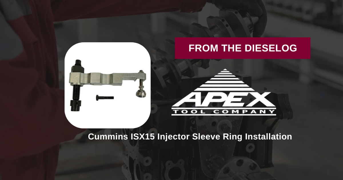
Repairing a fuel-contaminated cooling circuit or running a top-end overhaul on a Cummins diesel engine? Learn the professional technical sequence to press expansion rings safely using the ATC 5394735 tool set.

Why Asymmetrical Hammering Distorts the Precision Fuel Sleeve Lip
The fuel injector sleeves inside a Cummins CM2350 or X15 cylinder head are engineered to manage extreme fluid containment boundaries. To secure this tight mechanical fit, an internal expansion ring must be driven deep inside the cup to flare out its sealing lip flat against the cast iron well. When a line technician attempts to drive this high-tension ring home using a basic punch tool or standard hammer sockets, the force impacts at an angle. This asymmetrical distortion stretches the ring oval, cocking it inside the sleeve track. This lack of parallel alignment causes the copper walls to buckle, leading to an immediate fuel-water cross leakage pathway upon hot engine start. Utilizing a dedicated draw-plate fixture like the ATC 5394735 holds the components completely flat, driving the expansion ring down a dead-centered linear axis to lock down the seal cleanly.
The 5-Step Expansion Ring Seating Sequence
- Sleeve Inspection and Port Dressing: Pull the old fuel injectors. Extract the degraded sleeve rings. Wire-brush the internal receiver bore aggressively with solvent to strip away hard carbon scale, fuel glaze, and old sealant down to clean, bright metal.
- Position the Fresh Injector Sleeve & Ring: Drop your fresh injector sleeve firmly down into its target head port well. Set the new expansion ring straight and level onto the upper lip track of the sleeve casing, ensuring it does not tip sideways.
- Mount the ATC 5394735 Installer Plates: Align the heavy 5394731 and 5394732 installer plates flat over the cylinder head deck surface holes. Secure the guide anchor bolts (3910497 / 3946377) tightly into the cylinder head face threads to form an unyielding, dead-centered compression platform.
- Execute Controlled Mechanical Pressing: Lubricate the central draw bolt threads with clean engine oil. Thread the 5394947 heavy hex nut onto the center bolt shaft by hand. Slide on your manual 1/2" drive socket or a high-leverage breaker bar and turn clockwise smoothly. The parallel plates will compress evenly, pressing the expansion ring completely straight into the sleeve body.
- Bottom-Stop Verification & Final Inspection: Continue turning the heavy force nut down smoothly until you feel it hit a solid mechanical stop against the plate shoulder—indicating that the ring has expanded the sleeve to exact factory depth limits. Back off the forcing nut, pull the plates, and run a quick optical sweep down the clean well to verify a flat, perfect fit before mounting injectors.
PRO-TECH MECHANICAL IMPACT WRENCH BAN:
Never, under any circumstances, use high-speed pneumatic air or electric impact guns to run down the heavy forcing nut of your ATC 5394735 tool kit! High-frequency hammer strokes create severe force spikes that will gall the fine tool threads, strip out your cylinder head bolt tracks, or snap the expansion plate arms in half. Pull all final seating stages smoothly by hand using manual leverage.
6 lbs of Hardened Alloy Steel. Protect High-Pressure Common-Rail Boundaries.
Get the Cummins 5394735 Alternate Tool Now
overall rating:
my rating:
log in to rate