
Blog
Detroit DD13, DD15 & DD16 Counterbore Setup Steps
Precision tool calibration and engine block counterbore setup guidelines for commercial diesel mechanics and machine shops.

Calibrating counterbore cutter systems or dial depth indicators for Detroit Diesel DD13, DD15, or DD16 engine blocks? Follow this step-by-step professional workshop procedure to clean reference surfaces, configure the M50173 setting master for DD13 or DD15/DD16 applications, attach indicator extensions, establish an absolute zero point, and execute precision counterbore passes.
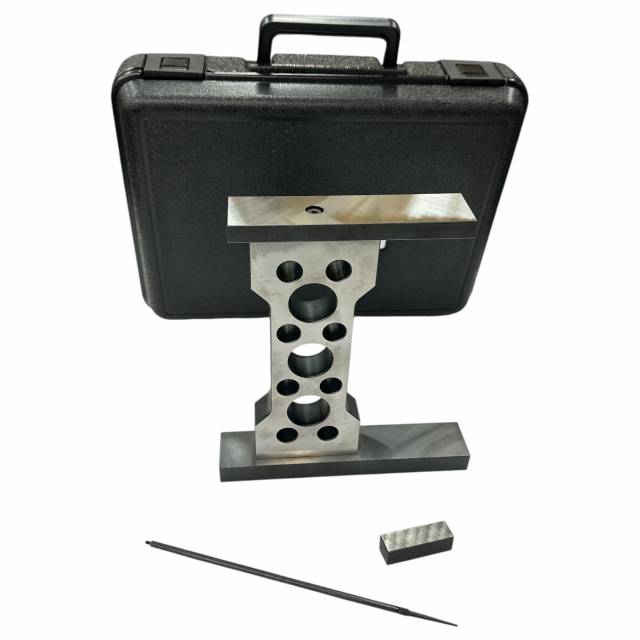
Why Direct Deck Zeroing Destroys Detroit DD-Series Engine Blocks
On Detroit Diesel DD13, DD15, and DD16 heavy-duty engines, cylinder liner counterbore depth directly governs liner protrusion, head gasket fire ring compression, and deck sealing. When counterbores suffer fretting erosion, machining the ledge and installing counterbore shims is required. However, zeroing a cutter assembly or dial indicator directly on an unmachined engine deck introduces severe errors. Used block decks develop fretting burrs, carbon staining, rust scale, and minor deck bowing. Zeroing an indicator on a deck high spot shifts your zero reference by several thousandths of an inch. If a machinist cuts a DD-series counterbore too deep, the block is permanently damaged—restoring it requires extensive sleeve machining or block replacement costing thousands of dollars. Utilizing the 11-pound M50173 Counterbore Setting Master completely prevents over-machining disasters. By establishing a ground reference standard away from the engine, technicians lock in true zero on the master fixture, ensuring every counterbore cut on the block matches factory depth specifications.
The 5-Step M50173 Calibration & Counterbore Setup Protocol
- Clean Master Fixture & Configure Engine Platform: Clean all ground reference faces of the M50173 setting master with solvent and lint-free towels. For DD15 or DD16 setups, use the main fixture base. For DD13 setups, install the included DD13-specific setting block onto the master.
- Mount Indicator Extension Arm: Attach the included indicator extension arm to your dial depth indicator stem. Mount the indicator assembly securely into the M50173 setting master holder.
- Zero the Dial Indicator on Ground Reference Face: Lower the indicator tip onto the ground reference face of the M50173 master. Rotate the dial bezel to align "0" with the indicator needle, then lock the bezel screw firmly.
- Transfer Calibrated Cutter Plate to Engine Block: Mount your calibrated cutter system—the M50166 kit (50167 cutter plate) for DD15/DD16 or the M50169 kit (50170 cutter plate) for DD13—onto the target cylinder of the engine block.
- Execute Counterbore Pass & Verify Final Depth: Advance the 50167-3 carbide bit to target depth based on your calibrated zero reference. Machine the counterbore ledge, clean shavings, and verify finished depth with the calibrated dial gauge before selecting shims.
PRO-TECH SOLVENT CLEANING & DIAL INDICATOR MANDATE:
ALWAYS WIPE REFERENCE SURFACES WITH SOLVENT BEFORE ZEROING! Microscopic dust or oil films WILL alter dial gauge zeroing by thousandths of an inch! REMEMBER: THE M50173 INCLUDES THE EXTENSION ARM BUT DOES NOT INCLUDE THE DIAL INDICATOR ITSELF—technicians must supply a calibrated dial depth gauge!
11.00 lbs Precision 3-Platform Counterbore Calibration Master. Protect Detroit Overhauls.
Get the M50173 Setting Master Now
overall rating:
my rating:
log in to rate