
Blog
Tech Guide: Detroit DD13/DD15/DD16 Counterbore Setup Steps
Precision deck machining guidelines for commercial fleet and Class 8 mechanics.
Machining counterbore ledges on a Detroit DD13, DD15, or DD16 engine deck? Follow this step-by-step professional workshop procedure to configure the M50173 setting master, mount your dial indicator extension, zero the cutter depth away from the engine, and execute precise counterbore cuts.
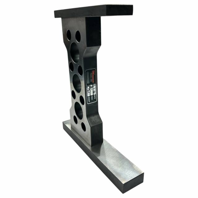
Why Direct-on-Block Setup Causes Destructive Machining Errors
Counterbore machining on modern Detroit Diesel engines requires accuracy down to thousandths of an inch. When counterbores become fretted or eroded from engine operation, installing new liners requires cutting the ledge deeper and placing precision shims beneath the liner flange. A common technician mistake is attempting to zero the cutter tool's dial indicator directly against an un-machined cylinder deck landing. Because worn deck landings are uneven, carbon-stained, or fretted, zeroing on them establishes an incorrect baseline. If the indicator reads off a recessed pit, the cutter bit will be set too deep, over-machining the block and ruining the counterbore seat. Utilizing a dedicated bench reference fixture like the 11-pound M50173 Setting Master isolates setup calibration completely. By resting the cutter assembly onto a mirror-ground, factory-calibrated steel reference surface, the machinist zeroes the dial indicator against a known standard. Once calibrated, the cutter tool is transferred to the engine block, guaranteeing that every cut matches exact Detroit DD-series counterbore shim specifications.
The 5-Step Counterbore Setup & Calibration Protocol
- Select Platform Configuration (DD13 vs DD15/DD16): Inspect target engine block specs. For DD15 and DD16 applications, use the primary master base. For DD13 engines, install the included modular DD13 setting block onto the master base landing.
- Mount Dial Indicator & Extension Stem: Thread the included indicator extension stem into your shop dial indicator. Secure the indicator into the counterbore tool cutter assembly or setting fixture bracket.
- Position Cutter Assembly on M50173 Master: Rest the counterbore cutter tool plate (M50166 / 50167 for DD15/DD16 or M50169 / 50170 for DD13) flat and square onto the precision-ground landing face of the M50173 setting master.
- Zero Dial Indicator & Set Cutter Depth: Lower the indicator stem onto the master reference anvil. Rotate the outer bezel dial to set the needle to absolute ZERO. Adjust the carbide cutter bit (50167-3) until it aligns precisely with target shim depth requirements.
- Transfer Cutter to Block & Execute Machining: Lift the calibrated cutter assembly off the M50173 master and bolt it securely to the target cylinder deck head bolt holes. Advance the micro-feed spindle and machine the counterbore ledge to exact calibrated depth. Clean chips, install shims, and verify liner protrusion.
PRO-TECH DIAL INDICATOR & CLEANLINESS MANDATE:
Remember: a dial indicator is NOT included with the M50173 kit! Always supply a calibrated 0.001″ or 0.0001″ AGD dial indicator. Ensure reference surfaces on the M50173 master and cutter plate are 100% free of dirt and grit before zeroing to prevent micro-calibration errors!
11 lbs Precision Steel Setup Master. Protect Detroit Engine Blocks.
Get the M50173 Setting Master Now
overall rating:
my rating:
log in to rate