
Blog
Heavy Diesel Counterbore Sleeving & Machining Steps
Precision cylinder block restoration guidelines for commercial diesel machinists and engine rebuilders.
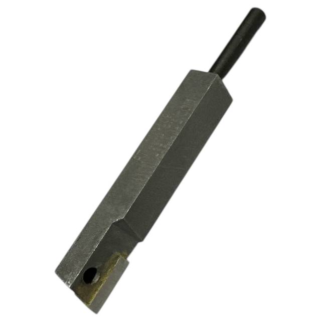
Resurfacing damaged engine block counterbores to install press-fit repair sleeves? Follow this professional machinist procedure for setting up your PT-2050-D tool head and taking clean, controlled passes with the PT-2000-109 carbide bit.
Why Rough Counterbore Seats Cause Sleeve Sinking & Block Failure
Installing a press-fit repair sleeve into a damaged counterbore requires precision depth control and a perfectly flat landing seat. When a machinist attempts to cut the sleeve recess using a worn or chipped cutter insert, the tool bit chatters across the hard cast iron. This leaves micro-ridges and uneven steps at the bottom of the counterbore ledge. Even though a repair sleeve may press in tightly initially, the immense clamping pressure from the cylinder head bolts and firing loads eventually flattens these rough ridges. As the metal flattens under load, the sleeve drops lower into the block—taking the cylinder liner down with it. The loss of liner protrusion breaks the head gasket fire-ring seal, causing immediate combustion pressure leaks into the coolant system. Utilizing a sharp, application-specific carbide insert like the PT-2000-109 ensures smooth chip removal and a mirror-flat bottom ledge that supports press-fit shims and sleeves permanently.
The 5-Step Sleeving Machining Protocol
- Inspect & Measure Damaged Counterbore: Thoroughly clean carbon, scale, and rust from the damaged counterbore. Measure the depth and wall damage using a dial depth indicator at 4 points (90 degrees apart) to calculate the required sleeve depth and thickness.
- Mount the PT-2000-109 Bit into the Tool Head: Inspect the PT-2000-109 carbide bit edge for any chips or defects. Secure the bit tightly into the PT-2050-D or M52050 cutter head assembly, ensuring the set screw holds the bit shank flat against the tool holder landing.
- Rig Rigid Tooling Centering on Deck: Position your counterbore machine fixture squarely over the target cylinder bore and anchor it rigidly to the deck face using the head bolt holes. Verify that the cutter spindle spins freely and is centered perfectly with the cylinder bore axis.
- Execute Controlled Light Machining Passes: Zero the PT-2000-109 cutter bit on the lowest damaged point of the counterbore ledge. Set the feed depth for light passes (typically .001" to .003" max per pass) and run the drive unit at the recommended cutting speed. Continue taking light passes until the counterbore wall and bottom seat are completely clean, flat, and uniform across 360 degrees.
- Clean, Verify Depth & Press Repair Sleeve: Vacuum away all cast iron chips and wipe the counterbore dry with solvent. Verify depth specs across four quadrants with a dial gauge. Apply recommended sleeve retaining compound and press the sleeve into position using a hydraulic or mechanical press tool before machining the final liner seat to factory spec.
PRO-TECH MACHINING SPEED & FEED DIRECTIVE:
Always maintain steady, continuous feed pressure and controlled cutting speeds when machining cast iron block counterbores! Taking excessively heavy cuts or forcing the tool bit through hard spots can chip the sharp carbide tip or induce chatter marks on the bottom seat. Light, controlled passes prolong bit life and yield the smoothest surface finish.
High-Density Carbide. Mirror-Smooth Counterbore Recesses.
Get Your PT-2000-109 Carbide Bit Now
overall rating:
my rating:
log in to rate