
Blog
Caterpillar Cylinder Liner Height Measurement Steps
Precision engine block deck metrology guidelines for commercial fleet and equipment machinists.
Executing an in-frame rebuild or counterbore repair on a Caterpillar C15 or 3406 engine? Learn the proper technical sequence to clamp liners, zero the sled gauge, and record four-point protrusion profiles using the M10246 / 1P-2402 gauge tool.
Why Unclamped Liner Measurement Leads to Blown Head Gaskets
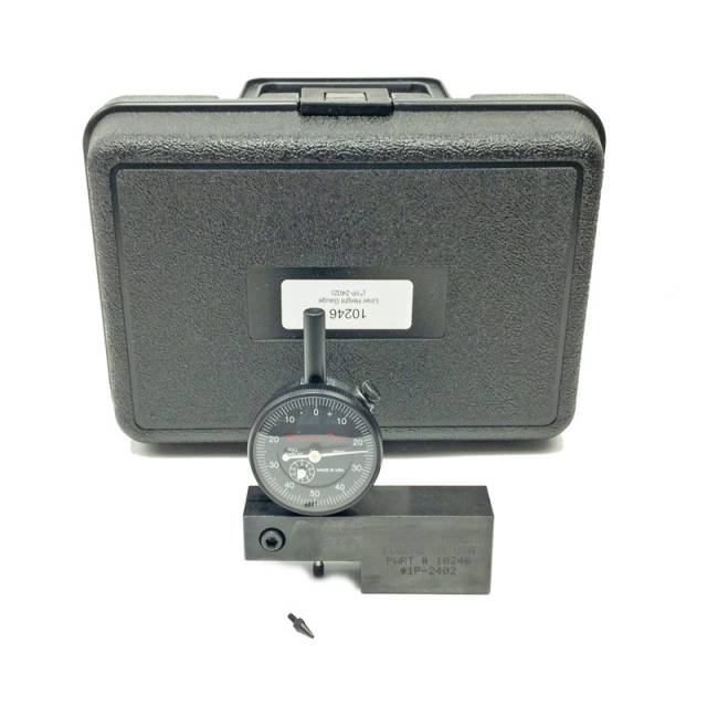
On Caterpillar wet-liner engine blocks, the cylinder liner sits on a counterbore ledge, sealed with lower rubber O-rings and upper filler bands. A common technician error when measuring liner height is taking readings while the liner is resting unclamped in the bore. The uncompressed lower O-rings push the liner upward, giving a false, inflated protrusion reading. When the cylinder head is later torqued down, the O-rings compress and the liner drops down lower than expected, resulting in zero head gasket fire ring crush. Furthermore, taking readings on an un-cleaned block deck or using a tipped gauge sled skews measurements by several thousandths of an inch. Utilizing the M10246 Liner Height Gauge requires clamping the liner down with hold-down bolts and washers to simulate full head torque, zeroing the precision-ground sled face on the bare deck, and measuring four distinct points around the liner rim to guarantee a 100% accurate, leak-free installation.
The 5-Step Liner Height Measurement Protocol
- Deck & Counterbore Triage: Thoroughly scrape away all old head gasket material, carbon, and scale from the block deck face and counterbore ledges. Clean the surfaces bone-dry with solvent. Inspect the counterbore ledge for fretting or pitting before installing fresh liners and shims.
- Install & Clamp the Liner Assembly: Install the cylinder liner (with shims if counterbores were machined) into the block bore without lower O-rings initially for test fitting. *CRITICAL: Install liner hold-down bolts and heavy flat washers on adjacent head bolt holes, torquing them to specified hold-down tension (e.g., 50–70 lb-ft) to fully seat the liner flange against the counterbore ledge.*
- Zero the M10246 Gauge Sled: Place the ground bottom face of the M10246 sled gauge flat on a clean, smooth area of the engine block deck face away from the bore edge. Press down firmly on the sled body and adjust the dial indicator bezel until the needle reads dead-zero.
- Record 4-Point Protrusion Readings: Slide the M10246 sled gauge across the deck until the indicator contact tip rests on the top flange of the clamped cylinder liner. Record the protrusion height at four equidistant locations around the liner circumference (12, 3, 6, and 9 o'clock positions).
- Analyze Variance & Adjust Shim Stack: Verify that all four readings fall within Caterpillar OEM specifications (e.g., +0.003″ to +0.006″) and that the variation around a single liner does not exceed 0.001″. Adjust counterbore shim thickness as necessary, repeat the measurement process across all cylinders, and record final heights on your overhaul build sheet.
PRO-TECH LINER HOLD-DOWN CLAMPING MANDATE:
Never measure cylinder liner protrusion without fully clamping the liner down to the block deck! Unclamped liners float on lower seal rings and provide completely false readings. Always use grade-8 bolts and heavy thick washers to torque the liner flange tight against the counterbore seat before applying the M10246 gauge!
Ground Steel Reference Sled. Protect Caterpillar Engine Rebuilds.
Get the M10246 Liner Height Gauge Now
overall rating:
my rating:
log in to rate