Blog
Tech Guide: Detroit 60 Series Injector Sleeve Extraction
Precision fuel component maintenance guidelines for high-volume commercial transport fleets.

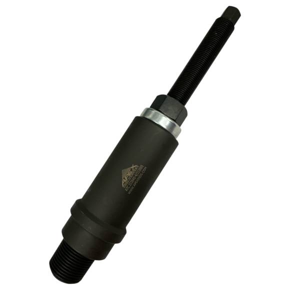
Dealing with localized combustion gas tracking back through your cooling lines? Learn the professional technical sequence to pull and press injector tubes cleanly with the ATC J33840-4 / J33880 tool.
Why Asymmetrical Impact Pullers Fracture Internal Valve Wells
The injection nozzle cavity on a four-valve Detroit Diesel Series 60 head is an exceptionally tight structural space. When a line mechanic attempts to extract a scale-welded injector cup using loose slide hammers or off-center wedge bars, the upward force strikes irregularly. This asymmetrical load forces the hardened steel tool to bind against the side wall, inducing micro-cracks or score marks in the soft cast iron receiver bore. Once scored, a fresh sleeve will never achieve an absolute crush-seal interface, leading to continuous post-build fluid cross-contamination. Utilizing a threaded, pilot-supported overhead draw fixture like the ATC J33840-4 / J33880 system ensures that extraction energy travels on a vertical path, keeping the cylinder head intact.
The 5-Step Injector Sleeve Overhaul Sequence
- Perform Workspace Cleanliness Audit: Pull the electronic fuel injectors. Clean out all carbon crust, oil scale, and residual debris from the injector cup interior face using a specialized wire brush. Stuff a clean, lint-free shop rag into the bottom nozzle hole to prevent cast chips from falling straight into the cylinder.
- Thread the Spent Sleeve Casting: Introduce the high-grade ATC kit tap assembly directly through the top center path of the worn cup. Turn the tap clockwise slowly using manual hand tools to cut clean, deep mechanical threads into the interior wall of the tube. Avoid pneumatic impact guns to prevent thread strip-outs.
- Lock and Draw the Core Out: Back out the tap and position the heavy tapped-cup mechanical remover adapter squarely over the freshly cut threads. Engage the primary overhead mechanical force nut clockwise. Wrench down smoothly—the centralized upward tension will cleanly snap the scaling bond and lift the tube straight out of the head bore.
- Bore Prep & Loctite Treatment: Vacuum out all remaining metal filings completely. Polish the receiver bore walls with a non-marring abrasive pad until bright metal is achieved. Clean the land with solvent. Apply a precise uniform bead of an approved high-temperature anaerobic block retaining compound along the lower and upper landing tracks of your fresh replacement sleeve.
- Drive the New Sleeve Home: Set the fresh copper or stainless steel tube squarely into the head port. Position the rigid ATC J33840-4 / J33880 driver-installer body over the core. Drive the sleeve forward using steady, axial force until it flat-bottoms flush onto the machined lower landing shoulder. Execute a strict visual inspection to confirm complete seating balance before final top-end button-up.
CRITICAL FIXTURE VARIATION INSIGHT:
The base ATC J33840-4 / J33880 tool kit comes configured to pull and press presized tubes right out of the box. However, when you are servicing highly specialized stainless steel cup lines (such as profiles 240-1039, 23538840, or 240-1045), remember that the supplementary internal trim cutters (parts M30161 and M30162) are sold separately and must be run in conjunction with this kit to complete the top-end flange shaving parameters post-installation.
Stop Fuel Cross-Contamination. Command Complete Precision.
Order the Sleeve Service Kit Now
overall rating:
my rating:
log in to rate