Blog
Complete Liner Height Measurement: Professional Procedure Using ATC1P-2402 Metric Gauge
Liner Height Measurement Procedure | Caterpillar Complete Guide
Complete Liner Height Measurement: Professional Procedure Using ATC1P-2402 Metric Gauge
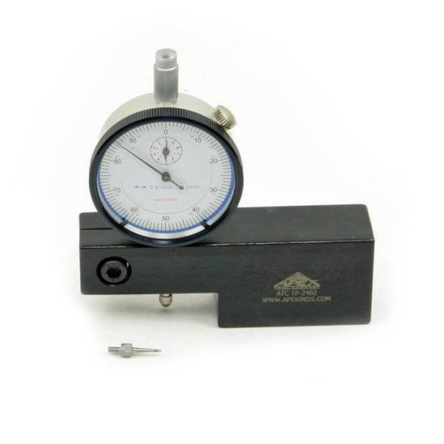
Precise liner height measurement on Caterpillar engines (3406, 3408, C15, and related series) determines head gasket compression and engine sealing integrity. This complete workflow guide covers the ATC1P-2402 Caterpillar Liner Height Gauge with metric dial indicator for professional engine rebuilds. From block deck preparation through final liner height verification and documentation, follow these steps for perfect OEM-specification measurements every time—eliminating measurement errors and protecting engine reliability.
GET LINER HEIGHT GAUGE NOW
Caterpillar Engines • Metric Measurement • Professional Workflow
Phase 1: Block Deck Preparation & Inspection
- Clean block deck thoroughly – Remove all oil, debris, and contamination from surface; use wire brush if needed.
- Inspect block deck for flatness – Check with straightedge for warping or damage.
- Clean all liner top surfaces – Remove any oil, dirt, or install lubricant; ensure dry, clean surfaces.
- Verify block deck is dry – Use compressed air to dry any wet areas; moisture affects gauge readings.
- Inspect for debris in block bores – Ensure no loose material inside cylinders that could affect measurements.
- Prepare measurement area – Ensure adequate workspace and stable surface for gauge operation.
Phase 2: ATC1P-2402 Setup & Dial Indicator Verification
- Inspect ATC1P-2402 gauge for damage – Check dial indicator, base, and measurement surfaces for cracks or bending.
- Verify metric dial indicator reads zero – Adjust if necessary before beginning measurements (per gauge instructions).
- Clean gauge measurement surfaces – Ensure base and contact points are clean; any debris affects accuracy.
- Familiarize with metric scale – Understand dial reading increments (0.01mm typical for quality gauges).
- Position gauge on clean work surface – Place gauge in stable position; avoid vibration or movement.
- Review Caterpillar OEM liner height specifications – Know the correct protrusion measurement before starting.
Phase 3: Block Deck Flatness Measurement (Sled Gauge Function)
- Set ATC1P-2402 to sled gauge mode – Configure for deck flatness measurement across block surface.
- Establish baseline reference point – Select one location as reference point (zero); record position.
- Measure across all cylinder locations – Move gauge across block deck systematically.
- Record deck flatness readings – Document each measurement location; identify high/low spots.
- Verify deck is within specification – Block deck typically must be flat within 0.05-0.10mm (per OEM).
- If deck is warped beyond spec – May require honing or surface finishing; consult OEM service manual.
- Clean block deck after flatness check – Remove any measuring dust or debris.
Perfect Liner Height = Reliable Engine
ORDER ATC1P-2402 NOW →Phase 4: Liner Protrusion Measurement
- Set ATC1P-2402 to liner protrusion mode – Configure gauge for height measurement above deck surface.
- Zero the dial indicator on block deck – Place gauge base flat on clean block deck surface; set dial to zero.
- Position gauge over first liner – Center gauge over liner top at cylinder #1 location.
- Lower gauge contact point onto liner top – Gentle pressure; allow gauge to settle naturally.
- Read dial indicator measurement – Note reading in metric units; this is liner protrusion height.
- Record measurement for cylinder #1 – Document in service record with cylinder location.
- Repeat for all cylinders – Measure protrusion on cylinders #2, #3, #4, #5, #6 (typical 6-cylinder).
- Document all protrusion readings – Create table with cylinder numbers and corresponding heights.
Phase 5: Counterbore Depth Measurement
- Switch to counterbore depth gauge mode – Reconfigure ATC1P-2402 for depth measurement.
- Zero gauge on block deck surface – Set dial indicator to zero baseline.
- Position gauge over counterbore area – Align gauge depth measurement probe over liner counterbore.
- Lower probe into counterbore recess – Gentle pressure; allow probe to bottom in counterbore cavity.
- Read counterbore depth measurement – Note dial reading; this is recess depth.
- Record depth for each cylinder – Counterbore depth should be consistent across all cylinders.
- Verify counterbore specification compliance – Compare measurements to Caterpillar OEM specifications.
Perfect Liner Measurement Ensures Reliable Engines
ADD TO CART • ATC1P-2402Phase 6: Liner Height Verification & Specification Comparison
- Review all liner protrusion measurements – Compare all cylinders; identify any inconsistencies.
- Check Caterpillar OEM specifications – Know correct liner protrusion range (typically 0.15-0.30mm).
- Verify uniformity across cylinders – All liners should have similar protrusion (within 0.05mm variation).
- If protrusion is out of specification – May require liner height adjustment or liner selection review.
- Compare counterbore depth consistency – Counterbore depths should be uniform across all cylinders.
- Document all measurement results – Create comprehensive service record with all readings and comparisons.
- Mark liners or block for reference – If any adjustments needed, mark locations for tracking.
- Proceed with head installation confidence – With perfect liner measurements confirmed, head installation can proceed.
Critical Warnings: Avoid These Mistakes
- ❌ NEVER skip block deck cleaning – Debris affects gauge accuracy and measurement reliability
- ❌ NEVER take measurements with wet surfaces – Moisture causes inaccurate dial readings
- ❌ NEVER use damaged gauge – Bent or cracked dial indicator produces false readings
- ❌ NEVER skip dial indicator verification – Always zero gauge before measurements
- ❌ NEVER apply excessive pressure to gauge – Gentle contact only; heavy force damages dial
- ❌ NEVER ignore specification limits – Out-of-spec measurements must be addressed before assembly
- ❌ NEVER skip documentation – All measurements must be recorded for service records
- ❌ NEVER compare metric to imperial measurements – Consistency is critical; use metric throughout
Precise Measurement = Perfect Engines
The Liner Height Gauge Every Caterpillar Shop Needs
BUY NOW → $200
✅ Caterpillar Engines • Metric Dial Indicator
✅ Multi-Function Measurement • Precision Accuracy
✅ Professional-Grade • Zero Measurement Errors
✅ Multi-Function Measurement • Precision Accuracy
✅ Professional-Grade • Zero Measurement Errors
overall rating:
my rating:
log in to rate