Blog
Tech Guide: Heavy Diesel Block Counterbore Re-Facing
Precision lower block deck restoration guidelines for commercial fleet mechanics.

Preparing for a lower engine re-sleeving procedure? Learn the strict mechanical sequence for machining and shimming worn engine block decks using the M50133 tool setup.
Why Tool Chatter Destroys Counterbore Seating Lands
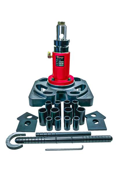
The ledge where a heavy-duty cylinder liner meets the engine block deck must be perfectly parallel to the crankshaft axis. When a technician attempts to re-face a corroded counterbore using a loose or lightweight cutter frame, the carbide tip induces tool chatter. This chatter leaves behind a wave-like pattern on the cast iron surface. When the engine is driven under load, the extreme combustion cycles collapse the repair shim into these gaps, causing the liner to settle and blow the cylinder head gasket. Utilizing a high-mass tool frame like the 56.00 lbs M50133 dampens mechanical vibration entirely, producing a flat finish that supports the liner flange evenly.
The 5-Step In-Frame Machining Protocol
- Execute Block Deck Mapping: Pull the old liners and scrape away carbon sludge. Use a precision dial indicator tracking gauge to measure the depth of the counterbore relative to the block deck at four opposing points. Document the lowest wear zone to determine your target cutting depth.
- Mount the Specific Cutter Adapter Plate: Select the application-specific cutter plate that matches your engine family (such as Caterpillar C15 or Cummins N14). Bolt the plate firmly to the base housing of the M50133. Install a fresh, premium **PT2200-93-6 cutter bit** into the tool arm.
- Anchor the M50133 Assembly: Lower the 56-pound tool assembly into the target cylinder bore until the self-centering guide indexes perfectly. Fasten the tool frame directly into the engine deck's structural cylinder head bolt holes to completely eliminate tool lift or drift.
- Execute Controlled Cutting Passes: Apply a light mist of cutting fluid to the carbide tip. Turn the manual drive handle slowly at a steady, rhythmic cadence. Advance the cutting feed knob incrementally, taking light passes to remove cast iron safely until a clean, uniform surface is achieved across the entire ledge.
- Verify Final Depth Metrics: Vacuum all cast filings completely out of the cylinder well. Wipe the machined surface clean with solvent. Use a micrometer depth gauge to calculate the exact repair shim thickness required to return your cylinder liner protrusion height to factory specification.
CRITICAL BIT CARE DIRECTIVE:
Never use pneumatic impact weapons or high-speed drills to actuate the drive shaft of an in-frame counterbore tool. The sudden, violent shock will chip the micro-edge of the premium PT2200-93-6 carbide cutter bit instantly, leaving deep grooves on the cast iron ledge. Always rotate the tool smoothly by hand to ensure a flat finish.
Industrial Machining Mass. Zero Tool Flex.
Order the M50133 Counterbore Tool
overall rating:
my rating:
log in to rate